The IBM Flex System Fabric EN4093 and EN4093R 10 Gb Scalable Switch is a high-performance networking device designed for virtualized environments, offering flexible and scalable solutions for data centers.
Function Description:
The IBM Flex System Fabric EN4093 and EN4093R 10 Gb Scalable Switch provides flexible, reliable, and high-performance features that meet the demands of today's highly virtualized environments. It serves as a crucial component within the IBM Flex System chassis, enabling connectivity for compute nodes and external networks. The switch supports both internal and external management, allowing for versatile deployment and configuration options. It can be managed through a Chassis Management Module (CMM) CLI, SSH/Telnet, or a web-based interface. The switch is designed to be installed in an IBM Flex System chassis, which can accommodate up to four I/O modules, including Ethernet switches, Fibre Channel switches, InfiniBand, and pass-thru modules.
Important Technical Specifications:
The base model of the scalable switch provides fourteen internal and ten external 10 Gb ports. There are two upgrades available for this switch:
- Upgrade 1: Adds forty-six 10 Gb ports.
- Upgrade 2: Adds support for sixty-four 10 Gb ports.
The switch has the following components:
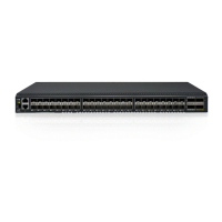
- Forty-two 10 Gb internal ports and twenty-two external ports: These are external ports arranged as fourteen SFP+ and two QSFP+ ports. The QSFP+ ports can be used as eight SFP+ ports.
- 10 Gb Ethernet switch supports single compute node port capability (fourteen ports): Dual compute node port capability (twenty-eight ports) and triple compute node port capability (forty-two ports) are available with optional licenses.
- Management and configuration: The switch can be managed and configured through a TTY/Telnet connection to the embedded command-line interface (CLI) or a Web browser-based interface (HTTPS/HTTP) connection.
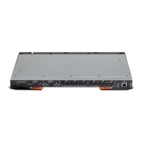
The switch module information panel contains the following components:
- LEDs: Display the status of the switch (OK, Identify, and Error) and the status of the external connections to the switch.
- Fourteen SFP+ module ports: These connectors are identified as ports EXT1 through EXT14 in the I/O-module configuration menus and are labeled 1 through 14 (from top to bottom) on the switch.
- Two QSFP+ port connectors: These can be used as eight SFP+ ports.
- One RS-232 serial port connector: For console port use (management purposes only). This connector is located near the bottom of the switch panel, just above the management (Mgmt) port.
- One RJ-45 Ethernet port connector: This connector is identified as port EXTM in the I/O-module configuration menus and is labeled Mgmt on the switch.
Status LEDs:
- OK (✓) LED (Green): Indicates the switch is on. If lit, the switch is operating correctly. If not lit, the switch is off. If yellow, it indicates a critical alert.
- Location (lighthouse icon) LED (Blue): Helps identify the location of a failed switch and is the result of a chassis user action.
- Switch error (!) LED (Yellow): Indicates a POST failure or critical alert. If lit, the system-error LED on the IBM Flex System chassis is also lit. If not lit, the switch is working correctly. If green, it indicates the switch is off.
Port Status LEDs (Link/Tx/Rx LEDs for Ports 1 through 22, Mgmt):
- Green: Indicates the corresponding port link is up and the status of the link activity for the corresponding port.
- Not lit: Indicates no signal on the corresponding port, or the link is down.
- Flashing green: Indicates there is an active connection (or link) between the corresponding port and the device that is using this connection.
- Lit green: Indicates the flashing, the corresponding port is connected and online, and link activity is occurring on that port.
Usage Features:
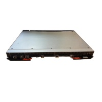
- Installation: The switch module is installed into an I/O bay of an IBM Flex System chassis. Proper handling of static-sensitive devices is crucial during installation. The installation process involves turning off power, attaching cables, and then turning the device on. The switch performs a Power-On Self-Test (POST) upon power-up, and LEDs indicate its status.
- Configuration: The switch supports various configuration methods. The default mode uses the internal path to the management module only. In this mode, the remote-access link to the management module must be attached to the Ethernet connector on the management module. The Internet Protocol (IP) addresses and SNMP parameters of the switch can be automatically assigned by the IBM Director Flex System Deployment wizard (when available), or you may assign them through the IBM Flex System Management and configuration program. The switch also supports external management mode, where external management is enabled, and the dedicated external management port (EXTM) or any of the external data ports (EXT1-EXT22) in-band access management is used.
- Firmware Updates: The switch firmware can be updated using a server application or through the SSHv2/Telnet interface from the management module. This process involves logging into the CMM CLI, setting the environment to the bay where the switch is installed, and executing commands to update the firmware.
- Licensing: The base option for IBM Flex System Fabric EN4093 and EN4093R switches supports twenty-four total data ports (fourteen compute node ports and ten uplink ports). Licenses are available to enable the use of additional ports on the switch. Upgrade 1 adds fourteen internal ports (15 - 28) and two external 10 Gb ports (57 and 61). Upgrade 2 adds fourteen internal ports (29 - 43) and four external 10 Gb ports (53 - 56). Licenses are unique to each switch and are non-transferable.
- Connectivity: The switch supports various cable types for connectivity, including SFP+ and QSFP+ modules for fiber optic connections, and RJ-45 cables for management ports. The serial console cable is used for direct connection to the switch for management purposes.
Maintenance Features:
- Troubleshooting: The switch provides basic troubleshooting information through POST errors and diagnostic indicators. Error codes are displayed on the management module switch information window. The
Application Guide and Command Reference provide more details about troubleshooting.
- Parts Listing: Replaceable components are categorized into Tier 1 customer replaceable units (CRU), Tier 2 customer replaceable units (CRU), and field replaceable units (FRU). Tier 1 CRUs can be replaced by the customer, Tier 2 CRUs require IBM to install them, and FRUs must be installed by trained service technicians. The manual provides a list of parts and their corresponding CRU numbers.
- Getting Help and Technical Assistance: IBM provides various resources for help and technical assistance, including online documentation, support portals, and contact information for IBM Support. Users can submit Electronic Service Requests for problem determination and resolution.
- Safety Information: The manual includes detailed safety statements and warnings regarding electrical current, laser products, and static-sensitive devices to ensure safe handling and operation of the switch.
- Environmental Notices: The manual provides information on particulate contamination limits, telecommunication regulatory statements, and electronic emission notices for various regions (FCC, Industry Canada, Australia and New Zealand, European Union, Germany, VCCI, Japan, Korea, Russia, People's Republic of China, and Taiwan).
- Documentation Format: The publications for this product are available in Adobe Portable Document Format (PDF) and can be downloaded from the IBM website.