EasyManuals Logo

IBM FlashSystem 900 User Manual

IBM FlashSystem 900
24 pages
To Next Page IconTo Next Page
To Previous Page IconTo Previous Page
Page #5 background imageLoading...
Page #5 background image
FlashSystem 900 Product Guide 5
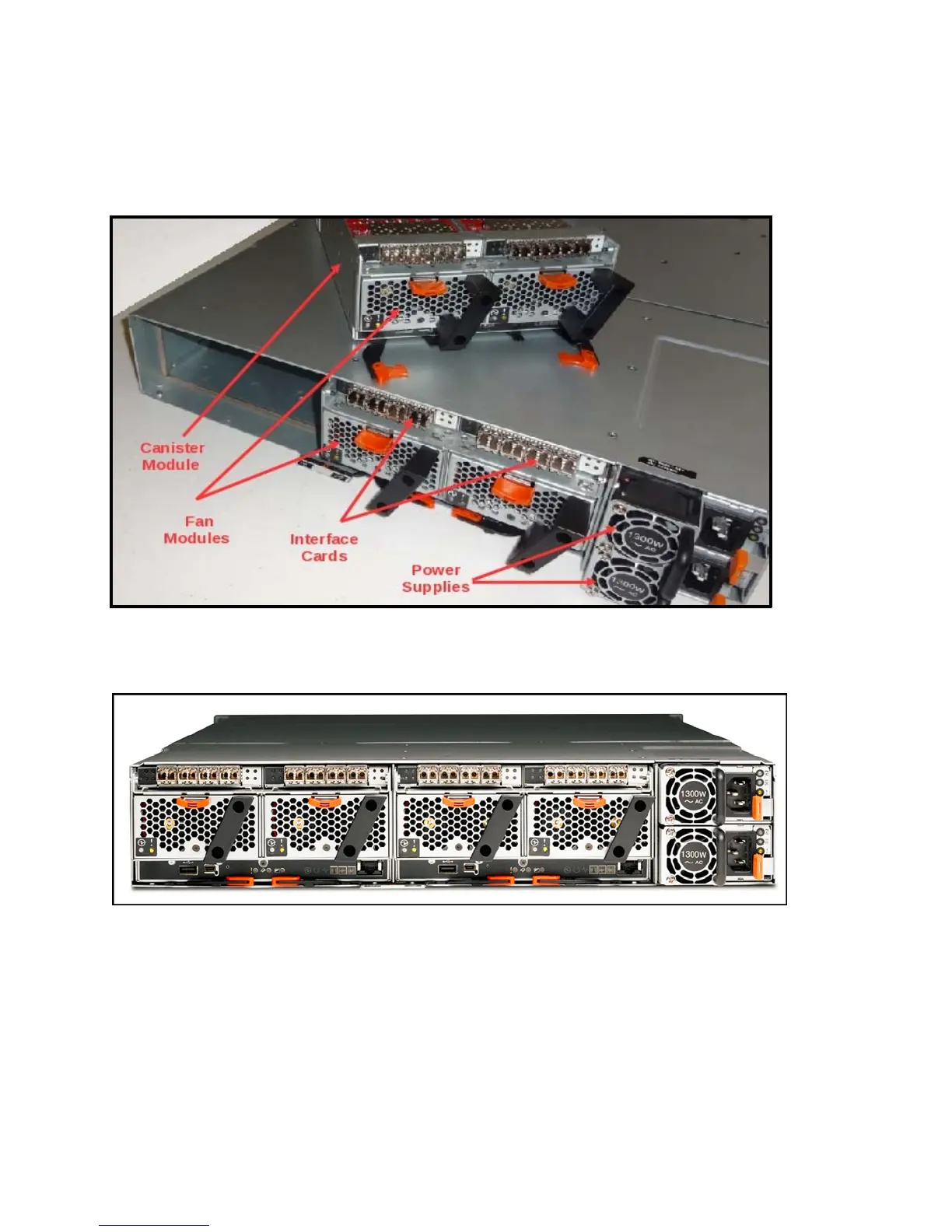
Figure 4 shows the components of IBM FlashSystem 900 from the rear. One of the two canisters is
removed, and you see two interface cards and two fan modules. The power supply unit to the right of the
fans provides redundant power to the system. All components are concurrently maintainable except for
the passive midplane, enclosure LED board, and power interposer board. All external connections are
from the rear of the system.
Figure 4. Rear view of FlashSystem 900 with one canister removed
Figure 5 shows a rear view of FlashSystem 900 with Fibre Channel or FCoE interfaces. The canisters are
to the left (large units) and the two power supply units are to the right (small units).
Figure 5. Rear view with Fibre Channel interface cards

Questions and Answers:

Question and Answer IconNeed help?

Do you have a question about the IBM FlashSystem 900 and is the answer not in the manual?

IBM FlashSystem 900 Specifications

General IconGeneral
ModelIBM FlashSystem 900
CategoryDisk array system
Maximum Capacity57 TB
Flash Module Capacity1.2 TB, 2.9 TB, 5.7 TB
Form Factor2U
Storage CapacityUp to 57 TB
Number of Flash ModulesUp to 12
InterfaceFibre Channel, InfiniBand
RAID SupportRAID 5
Power SupplyDual redundant, hot-swappable
Operating Temperature10°C to 35°C (50°F to 95°F)
Warranty1 year
Flash ModulesMicroLatency modules

Related product manuals