Appendix A. Connector Pin Assignments
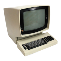
USB Connectors
4
3
2
1
Figure 10. USB Connector
The external interface for the USB ports consists of two, 4-pin connectors.
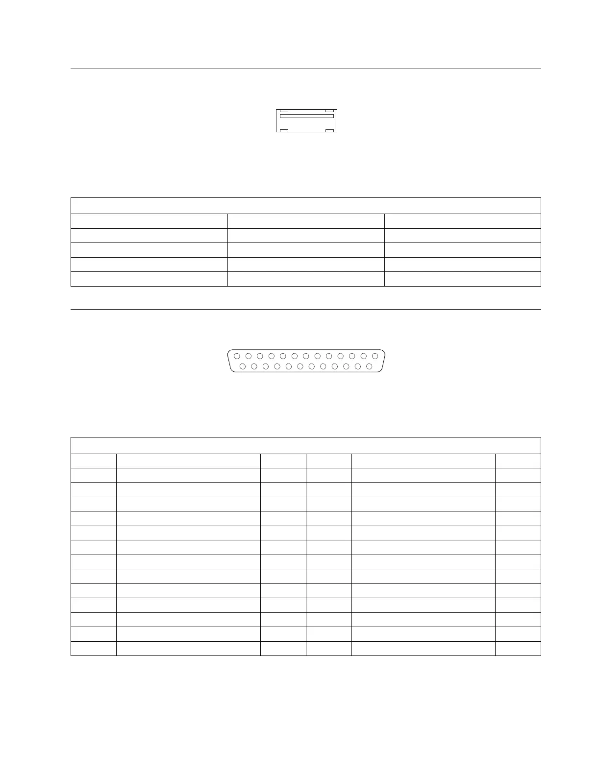
Parallel Port Connector
13
1
25
14
Figure 11. Parallel Port Connector
The external interface for the parallel port is a 25-pin, female, D-shell connector.
Table 44. Pin Assignments for the USB Connectors
Pin Signal Name I/O
1 VCC NA
2 -Data I/O
3 +Data I/O
4 Ground NA
Table 45. Pin Assignments for the Parallel Port Connector
Pin Signal Name I/O Pin Signal Name I/O
1 STROBE# I/O 2 D0 I/O
3 D1 I/O 4 D2 I/O
5 D3 I/O 6 D4 I/O
7 D5 I/O 8 D6 I/O
9 D7 I/O 10 ACK# I
11 BUSY I 12 PE I
13 SLCT I 14 AUTO FD XT# O
15 ERROR# I 16 INIT# O
17 SLCT IN# O 18 Ground NA
19 Ground NA 20 Ground NA
21 Ground NA 22 Ground NA
23 Ground NA 24 Ground NA
25 Ground NA
Appendix A. Connector Pin Assignments 49
 Loading...