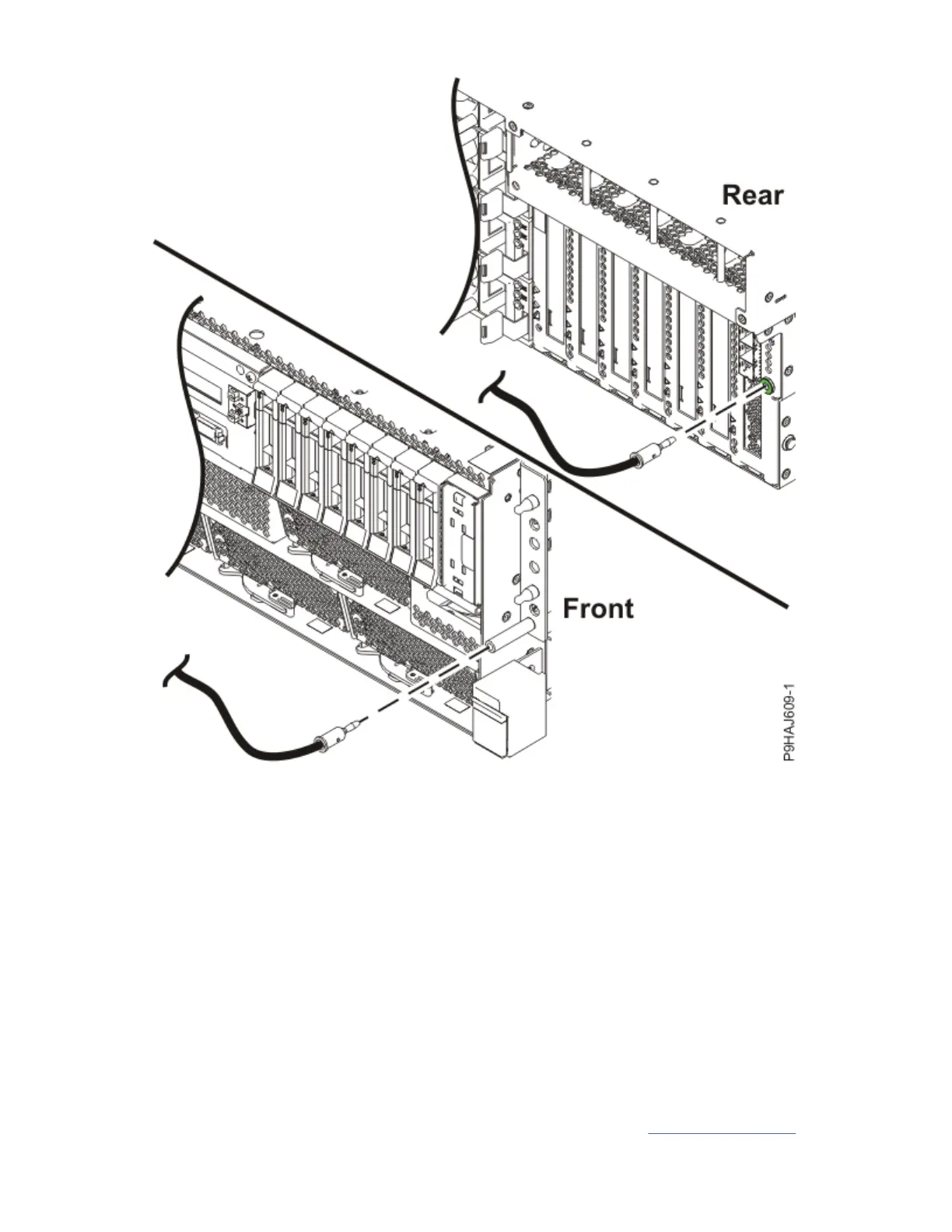
Figure 40. Location of ESD plugs
Removing the control panel display from the 9009-41A, 9009-42A, or 9223-42H system
To remove a control panel display, complete the steps in this procedure.
About this task
You must have at least one control panel display.
• The control panel display is required in the stand-alone tower system.
• In the rack-mounted system, a control panel display is required in one of the systems in that rack.
• If multiple systems are installed in multiple racks, a minimum of one control panel display is required in
each rack that contains the systems.
Procedure
1. Ensure that you have the electrostatic discharge (ESD) wrist strap on and that the ESD clip is plugged
into a ground jack or connected to an unpainted metal surface. If not, do so now.
2. Remove the control panel display (A) by pulling the tab (B) as shown in Figure 41 on page 43.
42
Power Systems: Power Systems: Control panel
 Loading...