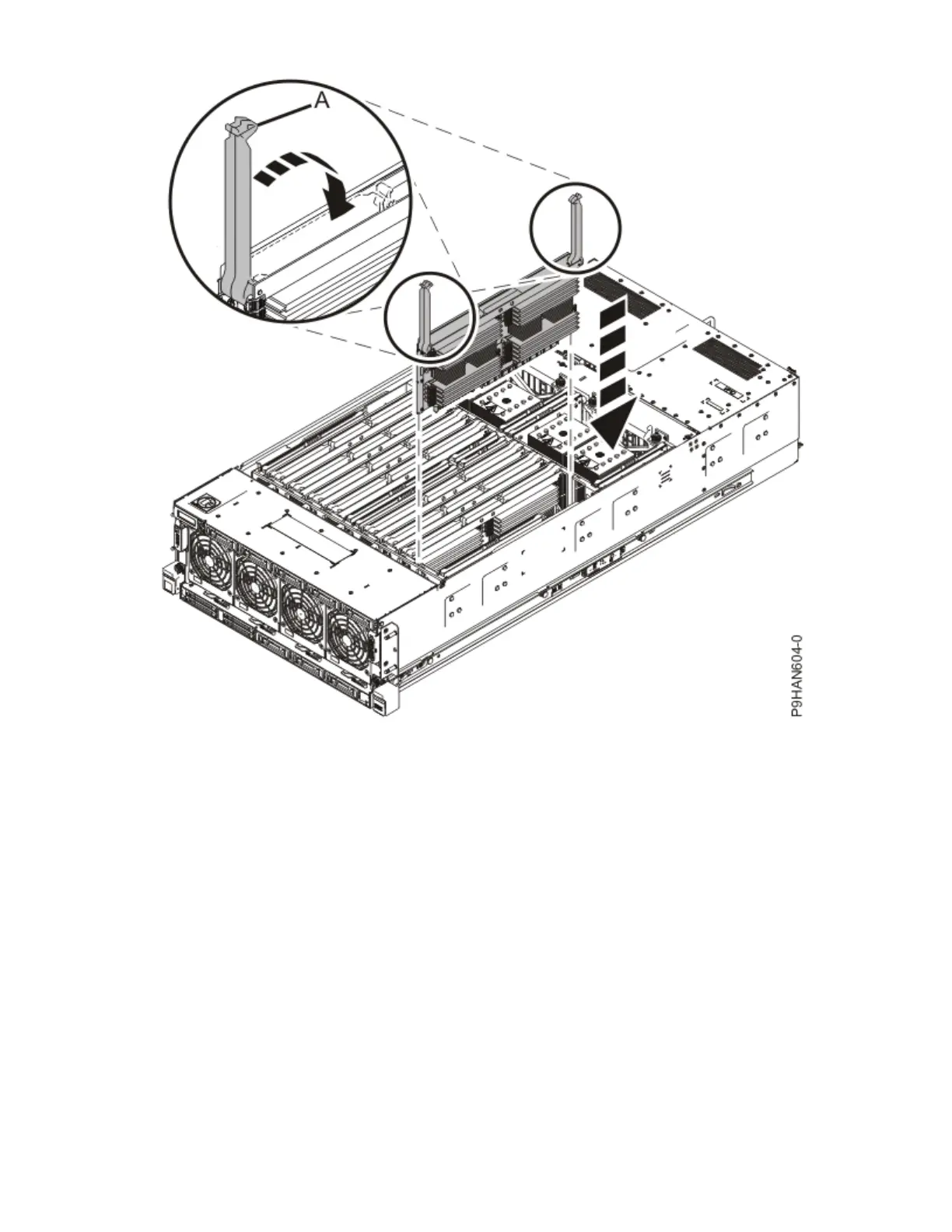
Figure 19. Inserting a memory riser
3. Replace the service access cover.
a) Lower the cover (A) onto the system unit. Ensure that the cover alignment pins (C) on each side of
the cover t into the matching slots in the chassis.
b) Slide the cover (A) onto the system unit. Ensure that the tabs (D) tuck under the mesh along the
front opening of the chassis.
c) Close the release latches (B) by pushing it in the direction that is shown in the following gure.
26
Power Systems: Power Systems: Memory