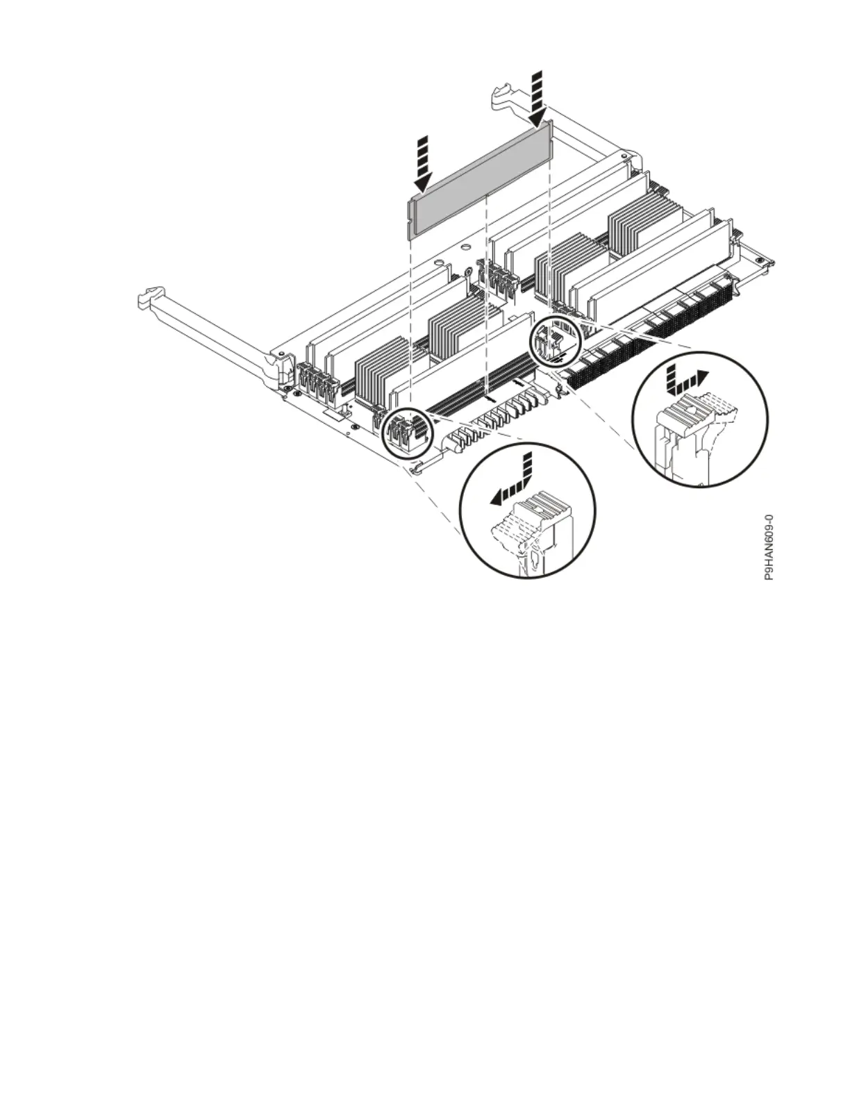
Figure 18. Replacing a memory module
Preparing the 9040-MR9 system for operation after removing and replacing a memory
module
To prepare the system for operation after you remove and replace a memory module, complete the steps
in this procedure.
Procedure
1. Ensure that you have the electrostatic discharge (ESD) wrist strap on and that the ESD clip is plugged
into a ground jack or connected to an unpainted metal surface. If not, do so now.
2. To insert the memory riser, complete the following steps:
a) Ensure the release latches (A) are fully open to a 90 degree angle as shown in the following gure.
b) Align the memory riser with the connector.
c) Press the memory riser rmly into the connector.
d) Rotate the release latches into the closed position, and press the release latches down to ensure
that the memory riser is fully seated into the connector.
Memory modules for the 9040-MR9
25