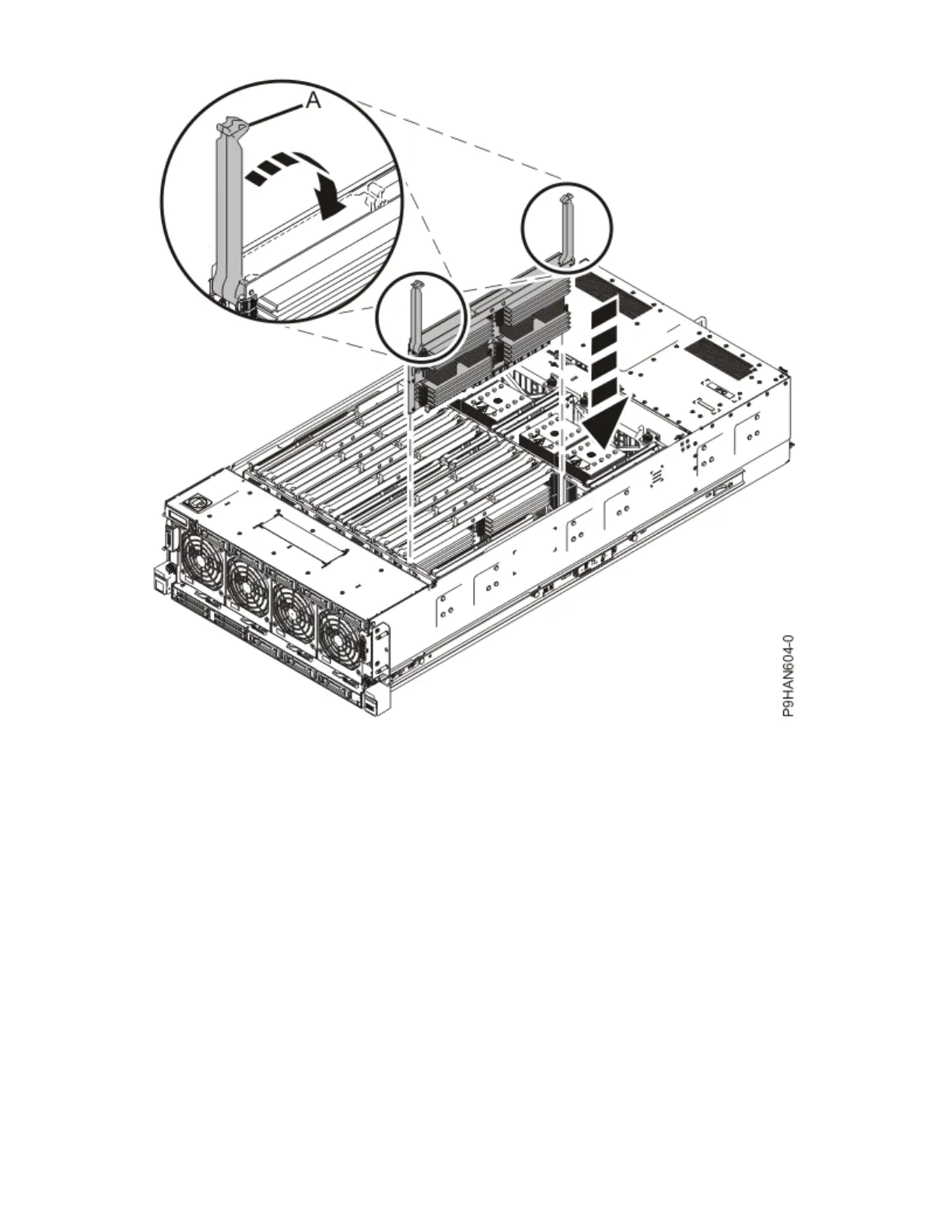
Figure 48. Inserting a memory riser
Preparing the 9040-MR9 system for operation after removing and replacing a memory
riser
To prepare the system for operation after you remove and replace a memory riser, complete the steps in
this procedure.
Procedure
1. Ensure that you have the electrostatic discharge (ESD) wrist strap on and that the ESD clip is plugged
into a ground jack or connected to an unpainted metal surface. If not, do so now.
2. Replace the service access cover.
a) Lower the cover (A) onto the system unit. Ensure that the cover alignment pins (C) on each side of
the cover t into the matching slots in the chassis.
b) Slide the cover (A) onto the system unit. Ensure that the tabs (D) tuck under the mesh along the
front opening of the chassis.
c) Close the release latches (B) by pushing it in the direction that is shown in the following gure.
66
Power Systems: Power Systems: Memory