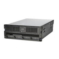
Figure 110. Installing the service access cover
4. Unlock the blue rail safety latches (A) as shown in Figure 111 on page 112 by pushing them inward.
Carefully push the system unit until it is 2.5-5 cm (1-2 in.) away from the rack.
Note: To allow enough room to attach the cable management arm, do not push the system unit all
the way into the rack.
Removing and replacing the system backplane in the 9009-41A, 9009-42A, or 9223-42H
111

 Loading...