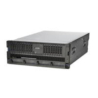
Figure 17. PCIe adapter slot locations in the 9009-41A, 9009-42A, or 9223-42H system
c) To set the adapter latch (A) at the target slot into the open position, rotate the latch (A) on the
rear of the system as shown.Figure 18 on page 21.
d) Carefully grasp the adapter (B) by its top edge or tailstock, and remove the adapter from the
slot.Figure 18 on page 21.
Attention:
A pin on the tailstock of the adapter resembles a removable screw. Do not
remove this pin. It is required for correct alignment and seating.
20 Power Systems: System backplane

 Loading...