Step 2
(from Step 1)
1. Except for the circuit breaker for the CPU enclosure, (typically the 50-amp circuit
breaker in position A1), set all of the circuit breaker switches to the Off position
(switches in the down position).
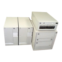
2. Label and record the locations of the power cords from the CPU enclosure and
the disk-drive-subsystem drawers to the power distribution panel.
3. Disconnect the power cables from the CPU enclosure.
4. Disconnect the power cables from the disk drive subsystem drawers.
5. Set all of the circuit breaker switches of the power distribution panel to the On
position.
6. Locate terminal board 2 (TB2) on the outside of the rear cover of the power
distribution panel.
7. Measure for -40 to -60 V dc on terminal board 2 (TB2) between positions one
and two (side A circuit breakers) and between positions five and six (side B
circuit breakers).
Is the voltage between -40 and -60 V dc?
NO Go to Step 3.
YES Before removing any circuit breakers, ensure that external power is not
present in the rack.
Exchange each circuit breaker until all of the circuit breakers are
exchanged or until -40 to -60 V dc is available. For information about
removing circuit breakers, refer to the “Circuit Breaker” removal and
replacement procedure on page 4-17.
If the symptom did not change and all of the circuit breakers are
exchanged, replace the power distribution panel.
Go to Step 5.
Chapter 5. Maintenance Analysis Procedures (MAPs) 5-5

 Loading...


