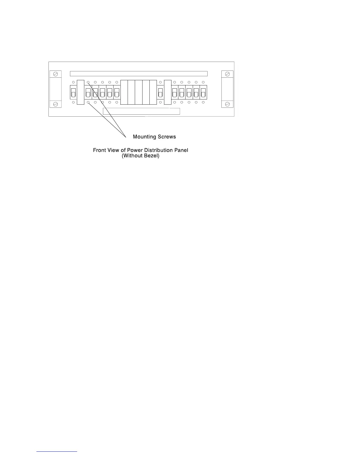
12. Remove the two mounting screws holding the front of the circuit breaker to the
PDP, and then remove the circuit breaker from the inside of the PDP.
Circuit Breaker Replacement
1. If the PDP is not powered off or disassembled, perform steps 1 through 7 in
“Circuit Breaker Removal” on page 4-17.
2. Attach the circuit breaker to the front of the PDP in the correct position using the
two mounting screws.
3. Fasten the rear of the circuit breaker to the PDP with the mounting nut.
4. Connect the -48 V DC power cable to the circuit breaker using the connector nut.
5. Connect the three wires that were labelled in “Circuit Breaker Removal” on
page 4-17 to the three connector pins on the rear of the circuit breaker.
6. If you are done replacing circuit breakers:
a. Replace the bus bar shield into the power distribution panel.
b. Ensure that the customer's technician properly connects the -48 V DC power
cables to the -48 V DC bus bars and the return power cables to the return
bus bars.
c. Replace the top cover of the power distribution panel and fasten with the six
mounting screws.
d. Replace the front bezel of the power distribution panel and fasten with the
two mounting screws.
e. Remove the warning tag or label from the switch at the customer's power
source.
f. Switch on power at the customer's -48 V DC power source.
4-20 7014 Model S00 Rack Installation and Service Guide
 Loading...


