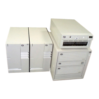
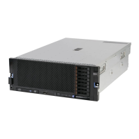
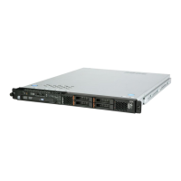
System Board Locations
J1
J2
J3
J5
J6
J7
J8
Memory Card Locations
Slot J1
Slot J3
Slot J4
Slot J2
Slot J5
Slot J6
Slot J9
Slot J10
Slot J11
Slot J12
Slot J13
Slot J14
Slot J15
Slot J16
Slot J7
Slot J8
Note: Memory modules must be installed in pairs and in the correct slot
configuration. (Slots J1 and J2, J3 and J4, J5 and J6, etc.)
J1 System board connector to I/O board
J2 Memory card 2 connector
J3 Memory card 1 connector
J5 Power supply connector
J6 Processor card connector #2
J7 Power supply connector
J8 Processor card connector #1
Chapter 1. Reference Information 1-7

 Loading...


