ICAR PQS ALL65 rev7 jan18
7 / 12
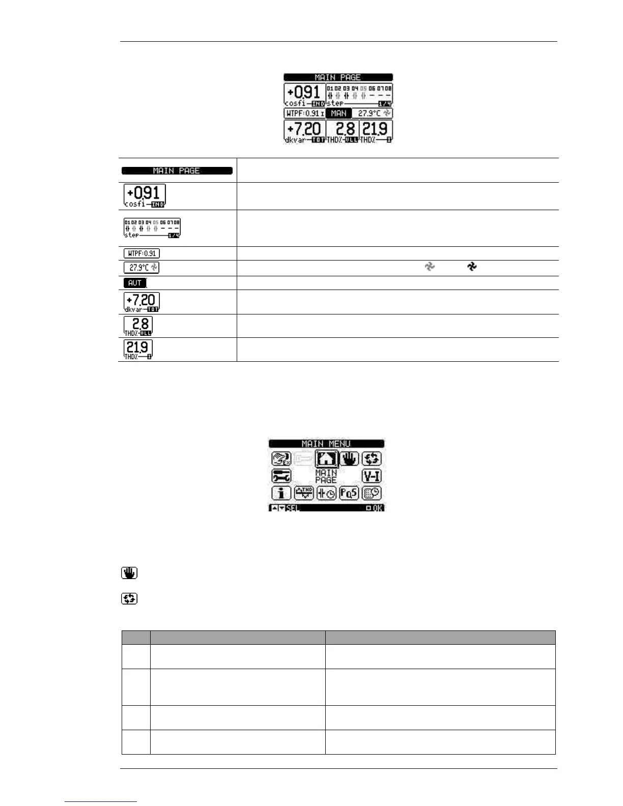
Main page
Descriptive text field. It can be changed from the SETUP menu
P01.09 SITE ID
System real time cosφ. IND= inductive, CAP= capacitive
. Black symbol: step inserted. Gray
symbol: step not inserted. Absent symbol: exit not used. Gray number: step
temporarily not available (for example: step just switched off)
Weekly true power factor, calculated on the last 7 days
Equipment internal temperature and fan status ( = stop; = start)
AUT= automatic mode; MAN= manual mode
indication) or reactive power in surplus (
indication) compared to the set target cosφ
Phase to phase voltage real time THD%
System current real time THD%, in the CT installation point
With the keys it is possible to move through the available pages. With the key, the MAIN MENU page is
accessed.
With the keys, to the display of additional steps that may be present in addition to those of the page 1/4 is
accessed.
Main menu
Select the desired menu with the keys and confirm with the key. The selected menu is highlighted in
reverse and at the centre a text description appears.
Select this icon to set the MANUAL MODE (MAN).
Select this icon to set the AUTOMATIC MODE (AUT).
Description and meaning of the alarms
CODE ALARM MEANING
A01 Under-compensation
All the available steps are connec
more inductive than the setpoint.
A03 Current too low
The current flowing in the current inputs is lower than
minimum measuring range.
This condition occurs normally if the plant has no load.
A04 Current too high
owing in the current inputs is lower than
minimum measuring range.
A05 Voltage too low
The measured voltage is lower than the threshold set with
 Loading...