WIRING DIAGRAM
(
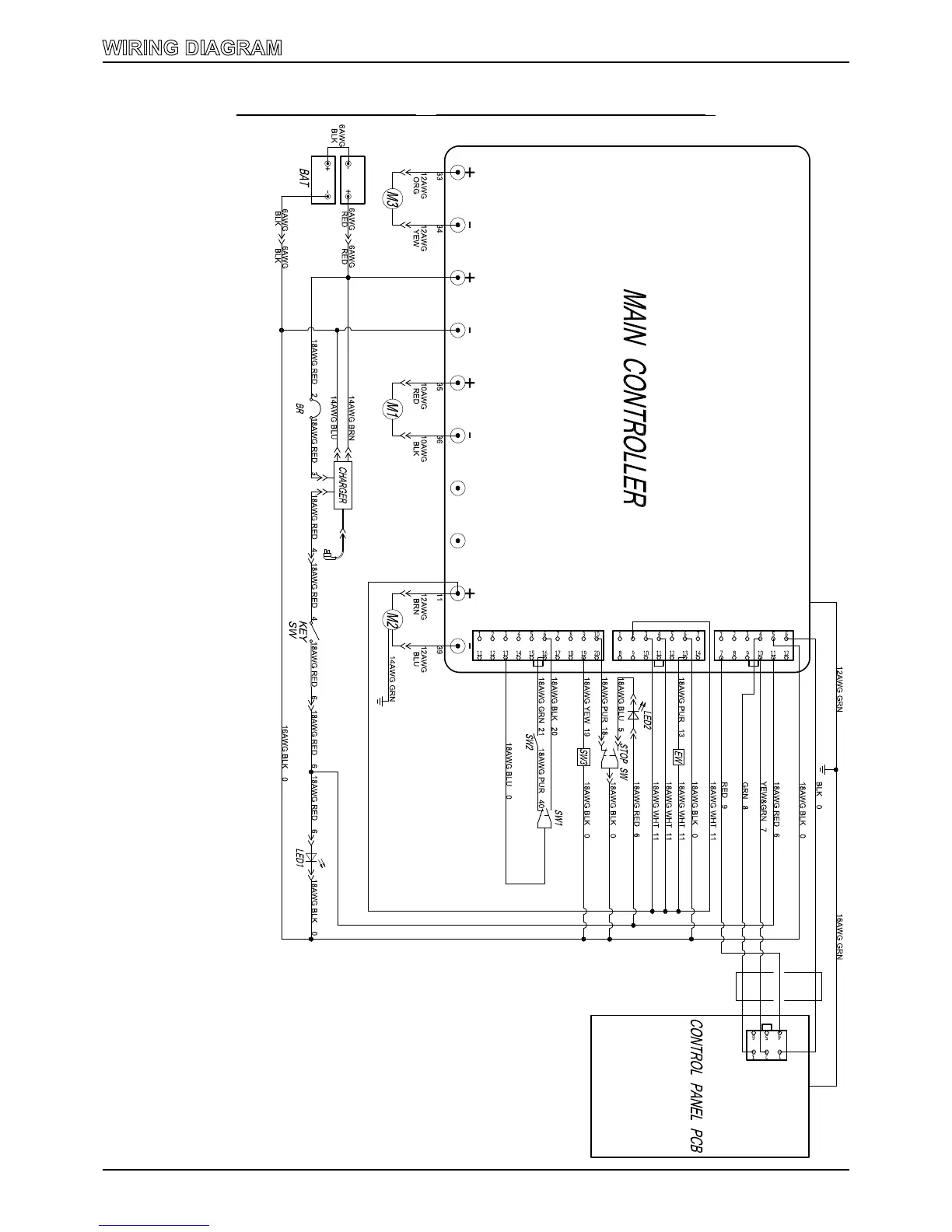
i20NBT, i20NBT-OB & i24BT
)
BAT: 2-12V Batteries
BR: Main controller circuit breaker
KEY SW: Main power key switch
LED1: Running light
CHARGER: On board battery charger
M3: Transaxle motor
M1: Brush motor
M2: Vacuum motor
SW2: Control handle bail switch, backward
SW1: Control handle bail switch, forward
SW3: Safe switch, scrub head lifting
STOP SW: Emergency stop switch
LED2: Emergency stop light
EW: Solution solenoid valve switch
MAIN CONTROLLER: Main controller
CONTROL PANEL PCB: Control panel PCB
 Loading...