9
The Ball Gate Assembly: Technical Informaon
Two half-moons aached together and connected to a single motor. The posion of the le half-moon is
sensed by two reed switches. A small magnet is located under the le moon. When the reed switch is
acvated, it will be at 0 VDC, the other will be opposite, +5 VDC.
On the main board at J14, pins 1 and 2 supply the voltage to the ball gate motor. Pins 3 and 4 are the sense
lines used to determine the posion of the ball gate. Located underneath the le side of the ball gate is a
magnet. When the gate is closed this magnet acvates the sensor aached to pin 3 taking the signal to
ground. Pin 4 will be at +5 VDC. When the gate opens, pin 4 will go to ground and pin 3 will have +5 VDC on
it.
If the magnet sensors are not ush to the wood surface, the magnet will not acvate the sensor causing the
ball gate to move pass the closed or open posion. When this occurs, the ball gate will shut down and only a
power cycle will allow the ball gate to work again.
If aer checking that the ball gate is not having a sensor problem, look at the linkage for any of the Grubb
screws that might have goen loose. Also look at the connector rod and make sure it is sloed and not
rounded out.
** Note ** If the game doesn’t see the open or close reed switches it will open the ball gate and not
aempt to run the ball gate motor again unl you power cycle the game.
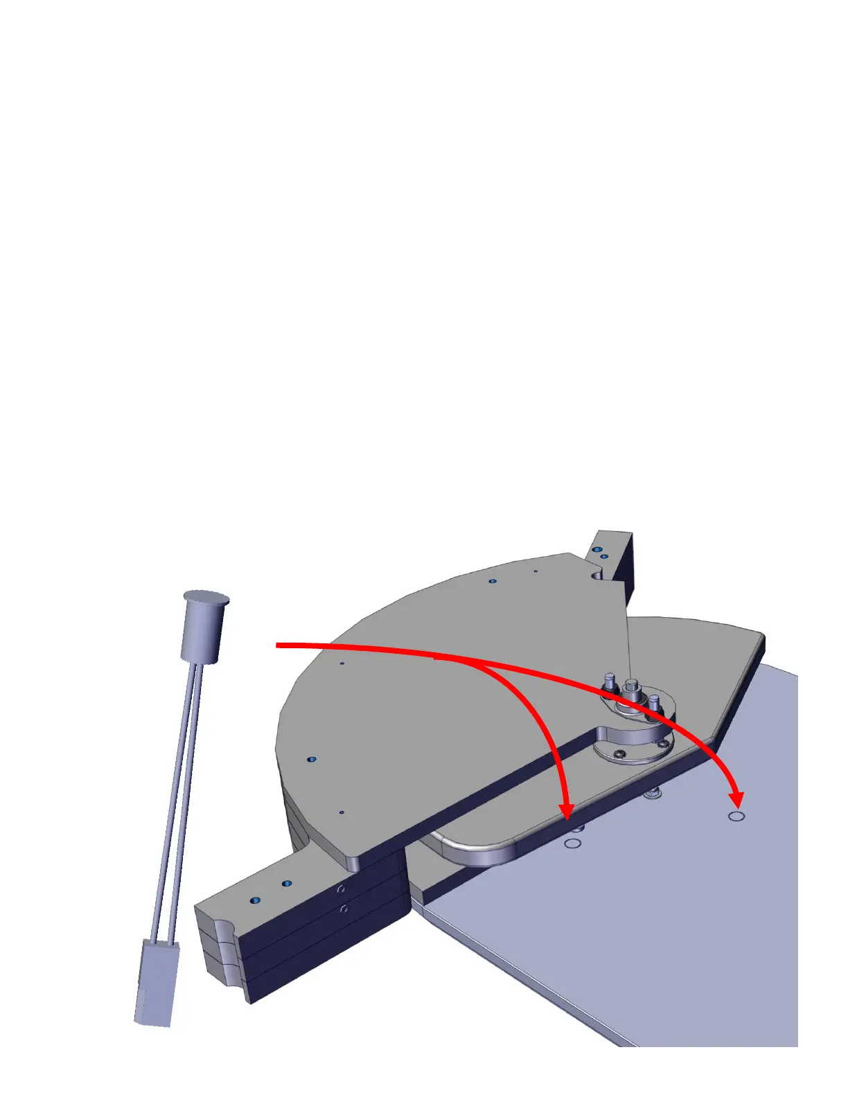
Reed switch embeds into the wood instead of being at the surface.

 Loading...