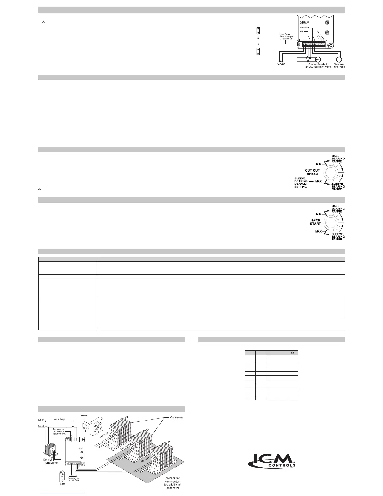
1.TheHeat Pumpterminalsacceptthe24VACsignalfromthereversingvalveholdingcoil.MakeaparallelconnectionfromthereversingvalvetotheHPterminals.
Note:Do not apply a voltage higher than 30 VAC to the HP terminals.
2.IftheHeat PumpisintheHeatingmodeandthereversingvalveisenergized,thentheHeat Pump Selectjumpermustbeinthe
Default(N.O.)position.
3.IftheHeat PumpisintheHeatingmodeandthereversingvalveisnotenergized,thentheHeat Pump Selectjumpermustbeinthe
N.C.position.
7313 William Barry Blvd., North Syracuse, NY 13212
(Toll Free) 800-365-5525 (Phone) 315-233-5266 (Fax) 315-233-5276
www.icmcontrols.com
ONE-YEAR LIMITED WARRANTY
TheSellerwarrantsitsproductsagainstdefectsinmaterialorworkmanshipforaperiodofone(1)yearfromthe
dateofmanufacture.TheliabilityoftheSellerislimited,atitsoption,torepair,replaceorissueanon-casecreditfor
thepurchasepricesofthegoodswhichareprovidedtobedefective.Thewarrantyandremediessetforthherein
donotapplytoanygoodsorpartsthereofwhichhavebeensubjectedtomisuseincludinganyuseorapplication
inviolationoftheSeller’sinstructions,neglect,tampering,improperstorage,incorrectinstallationorservicingnot
performedbytheSeller.InordertopermittheSellertoproperlyadministerthewarranty,theBuyershall:1)Notify
theSellerpromptlyofanyclaim,submittingdatecodeinformationoranyotherpertinentdataasrequestedbythe
Seller.2)PermittheSellertoinspectandtesttheproductclaimedtobedefective.Itemsclaimedtobedefective
andaredeterminedbySellertobenon-defectivearesubjecttoa$30.00perhourinspectionfee.Thiswarranty
constitutestheSeller’ssoleliabilityhereunderandisinlieuofanyotherwarrantyexpressed,impliedorstatutory.
Unlessotherwisestatedinwriting,Sellermakesnowarrantythatthegoodsdepictedordescribedhereinaretfor
anyparticularpurpose.
LIAF004-1
DuringtheHard Startmode,fullvoltageisappliedtothemotorduringstartuptoovercomewindmillingandtolubricatethebearings.
Thepositionofthehardstartdialdeterminesthetimeperiodofthehardstartmode.Thedialcanbeadjustedbetween0.1secondandapproximately5seconds.
Setthehardstartdialaccordingtothetypeofmotoryouhave.Ifyouhaveaball bearing motor,setthehardstartdialtotheMINposition.Ifyouhaveasleeve bearing motor,setthe
hardstartdialtothemiddleofthesleevebearingrange.
Afteryoubeginattherecommendedsetting,youcannetunethehardstarttimewithintherecommendedrangeforthetypeofmotoryouhave.
Itisrecommendedthatyouusetheminimumpossiblehardstarttimetoavoidblowingtoomuchcoldairoverthecondenser.
Hard Startmodeisactivatedwhen24VACisapplied(ordisconnectedandre-applied)ortheprobetemperatureincreasestoabove70°F.Thehardstartmodeappliesfullvoltagetothe
motorforthesettimeperiod.Afterwards,themotorspeedisdictatedbythetemperaturesensor(s).
Setting the Hard Start Speed
Thecutoutspeeddialadjuststhemotorvoltagerange.Setthecutoutvoltagedialaccordingtothetypeofmotoryouhave.
Sleeve Bearing Motors:
Setthecutoutspeeddialtothemiddleofthesleevebearingrange.Inthisrange,themotorcanrundownapproximately40-50%ofthefulllinevoltage,whichallows
sufcientRPMsforcoolingandlubrication.
CAUTION!:
Withsleevebearingmotors,itisimportantnottoadjustoutsidethesleevebearingrangeorbearingfailuremayresult.
Ball Bearing Motors:SetthecutoutspeeddialtotheMINpositionintheballbearingrange.Thispositionoffersthegreatestrangeofspeedcontrol.AttheMINsettingthe
motorcanrundowntoapproximately20-30%ofthefulllinevoltage.
Note:After starting at the recommended settings for either sleeve or ball bearing motors, you can ne tune the cutout speed to achieve the desired results.
Setting the Cutout Speed
Symptom Problem
Unitfailstostart Thesensormaynotbeconnectedoritisdefective.
Withtheprobedisconnected,useanohmmetertomeasuretheresistancebetweentheprobewires.ItshouldmatchthechartinAppendixB.IfyoureadanOPENor
SHORT,replacethesensor.
Fuseand/orcircuitblows Theunithasbeenmiswiredandmaybepermanentlydamaged.
ThefancyclesfromfullONtofullOFF
withlittleornomodulation
TurnOFFthecontrolcircuitpower(24VAC).Re-apply24VACpowerandconrmhardstartoperation.Reducethehardstartperiodtotheminimumsettingrequiredto
acceleratethefan.Excessivehardstartingcauseslargepressuredropsbyrunningtoomuchcoldairoverthecondenser.
Shouldthecyclingpersist,movetheprobeupseveralbendsintothecondensertoincreasethesensitivitytocondensingtemperature.
Adjustprobelocation.Finetunecutoutadjustment.
Thefandoesnotcomeonatall UsinganACvoltmeter,measurethevoltagebetweenthe24VACterminals.Itshouldreadapproximately24volts.
MeasurethelinevoltagebetweenLINE 1andLINE 2toconrmthatthelinevoltageispresent.
Removethethermistorprobefromtheterminalblockandmeasureitsresistanceatambienttemperature.Compareyourreadingattheappropriatetemperaturein
AppendixBtoseeiftheactualresistanceapproximatesthelistedvalue.Next,holdtheprobeinyourhandandconrmthattheresistancedecreases.
PlaceatemporaryjumperacrosstheS2orS3terminals.Fanshouldrunatfullspeed.Ifitdoes,recheckprobeconnectionandverifyprobeisoperatingcorrectly.
Thehighpressureswitchtripsoff Movetheprobefurtherintothecondenserwherethetemperatureishigher.ThiswillproduceahigherfanRPMandwilldecreasetheheadpressure.
Fineadjustthecutoutandhardstartsettings.
GreenandYellowLEDsalternate Verify24VACisavailableatthe24VACterminals.
Troubleshooting
Mounting a sensor into the condenservs. mounting it on the liquid line
Whenasensorismountedintothecondenser,thecontrolrespondsmorerapidlytochangesin
headpressurethanwhenitismountedontheliquidline.Thisisespeciallytrueforhighefciency
condensers.
Whenthesensorismountedontheliquidline,thecontrolrespondsmoreslowlyandtheresultscan
beafanthatcyclesonandoff.
Wheneverpossible,itispreferabletomountthesensorintheupper1/3ofthecondenserinsteadof
mountingitontheliquidline(seeillustrationbelow).Aspotonthecondenserthatis100°Fwhenthe
pressuresarecorrectisideal.
Appendix A
°C °F Resistance (K )
0° 32° 32.7
5° 41° 25.4
10° 50° 19.9
15° 59° 15.7
20° 68° 12.5
25° 77° 10.0
30° 86° 8.1
35° 95° 6.5
40° 104° 5.3
45° 113° 4.4
50° 122° 3.6
Temperature vs. Probe Resistance
Appendix B
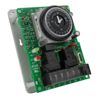
ICM325HNV Typical Installation
N.O.
N.C.
Connections for Heat Pump Systems
Normal Function
Withprobetemperaturesabove100°F,thecontrolappliesfullvoltagetothemotor.Thegreenlightis
illuminated(fullspeedLED).
Withprobetemperaturesbetween70°Fand100°F,themotorspeedisproportionaltotheprobe
temperature.Theyellowlightisilluminated(variablespeedLED).
Whenthemotorstartsattemperaturesbetween70°Fand100°F,itwillhardstartforthelengthoftime
dictatedbythehardstartdialsetting.Afterthehardstarttimehaselapsed,themotorspeediscontrolled
bytheprobetemperature.
Asthetemperaturebeingsenseddecreases,theoutputvoltagedecreases.Theoutputvoltagemay
decreasetothedeterminedcutoutspeeddictatedbythecutoutspeeddial.Uponreachingthecutout
speedsetting,theoutputvoltagegoestozerovolts.
Systemrestartwilloccurwhenthetemperatureexceeds70°F.
Withprobetemperaturesbelow70°F,themotorremainsoff.Thegreenlightandtheyellowlightareoff.
Mode of Operations
Heat Pump Bypass Operation
Heatpumpbypassmoderunsthefanatfullspeedwhenthesystemisoperatinginheatmode.This
movesasmuchairaspossibleacrossthecondensercoil.
IftheheatpumpselectjumperisintheN.O.position,and24VACisappliedtotheHPterminals,the
motorwillbebroughttofullspeed.
IftheheatpumpselectjumperisintheN.C.position,and24VACisnotpresentattheHPterminals,the
motorwillbebroughttofullspeed.
Aseparaterelayisnotneeded.

 Loading...