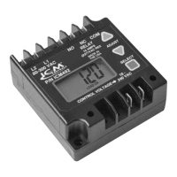
ICM492
Single Phase Digital Line Voltage Monitor
Reliable protection of single phase systems against adverse line voltage conditions
SPECIFICATIONS
User Adjustable Settings:
•Voltage setpoint:95-280V
•Anti-short cycle time delay:0-720sec.
•Over voltage setting:5-25%
•Under voltage setting:5-25%
•Control mode:OnandOff
•Response time:0.1to10seconds
Inputs:
•Line voltage:80to300VAC
•Control voltage:24to240VAC
•Frequency:50/60Hz
•Accuracy:±2%
•Low power consumption:Max50mA@120V,
Max100mA@240V
Output:
•Type:dryrelaycontacts
•Form:SPDT
•Relay contact ratings:
–N.C. Contacts:10Aresistive@277VAC
–N.O. Contacts:10Aresistive@277VAC
•Connection Terminals:0.25”malefast-on
Mechanical:
•Case dimensions:3”Lx3.2”Wx1.35”H
•Unit weight:0.36lbs.
Environmental:
•Operating temp. range:-30°Cto+70°C
•Storage temp. range:-40°Cto+85°C
•Maximum operating/storage relative humidity:
95%non-condensing
7313 William Barry Blvd., North Syracuse, NY 13212
(Phone) 315-233-5266 (Toll Free) 800-365-5525
(Fax) 315-233-5276
www.icmcontrols.com
LII335-3
Constantly monitors and displays line
voltage. Protects against Over and Under
voltage, and Rapid Short Cycling caused by
Transient Faults and Power Interruptions
TheICM492isspecicallydesignedtomonitorline
voltageandguardsinglephaseequipmentagainst
damagecausedbyunderandoverlinevoltage
conditionsandrapidshortcycling.Recordslastve
faults.
DESCRIPTION
•UniversalLineVoltage
Input
•Easy-viewBacklitDigital
Display
•RMSVoltageMonitoring
•5-faultmemorystorage
•AdjustableVoltageSet
Point
•AdjustableOverVoltage
SetPoint
•AdjustableUnder
VoltageSetPoint
FEATURES
•AdjustableAnti-Short
CycleTimeDelay
•AdjustableResponseon
FaultTime
•ControlMode
•5-FaultMemory
•UniversalControl
VoltageInput
•HeavyDutySPDTRelay
Output
TheICM492continuouslymonitorsincominglinevoltage
forfaultsanddisplaysRMSvoltageonthedigital
display.Whenlinevoltageisappropriate,ICM492closes
theCOMandN.O.relaycontacts.Whenincomingline
voltageisoutsideofuserselectedparameters,ICM492
willclosetheCOMandN.C.relaycontactsandindicate
afaultconditionbyashingFAULTondisplay.Theunit
recordsthelastvefaults,storingthehighestandlowest
voltagereadingsthatcausedthefault.TheUP,DOWN
andSELECTbuttonsarepressedsimultaneouslyto
clearthefaultsfrommemory.TheSELECTmenuhas
thefollowinguseradjustablesettings:voltagesetpoint,
timedelay,overvoltagepercentage,undervoltage
percentage,controlmode,andresponsetime.Time
delaypreventsshortcyclingwhenfaultnolongeris
presentandrapidpowerinterruptions.Theresponse
timeonthefaultconditioncanbeadjustedtohelp
reducenuisancetripsfromtransientfaults.When
ControlModesettingisselectedONthenICM492will
closeCOMandN.O.relaycontactsonlywhencontrol
voltageispresentatControlVoltageterminalsandthe
linevoltageisgood.Therelaycontactscanbeused
todirectdrivetheloadaslongascurrentratingisnot
exceeded.
MODE OF OPERATION
!!! WARNING !!!
ElectricalShockHazard
• Verify power is disconnected by removing a fuse
or opening a circuit breaker before making any
connections.
• This control should be installed by a trained technician.
• Incorrect installation can cause personal injuries,
property damage or death.
• Follow all local & national codes while installing control.