Installation, Operation & Application Guide
For more information on our complete range of American-made
products – plus wiring diagrams, troubleshooting tips and more,
visit us at www.icmcontrols.com
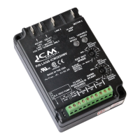
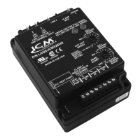
ICM325HNV
High Voltage Head Pressure Control with
Optional Heat Pump Override
Temperature sensitive control regulates head pressure
Caution!
Installation of the ICM325HNV shall be performed by trained technicians only. Adhere to all local and national electric codes.
Disconnect all power to the system before making any connections.
•Line voltage:120-600VAC
•Control voltage:18-30VAC
•Frequency:50-60Hz
•Operating temperature:-40ºFto+176ºF(-40°Cto+75°C)
•Sensors:10Kohmsat77°F(25°C)
•Heat pump override:24VACN.C.orN.O.
Note:A maximum of three sensors can be connected to the control.
•Weight:12ounces(341grams)
Note:The ICM325HNV should be applied to motors and equipment that have been designated by their respective manufacturers as capable of being speed controlled.
• Mounting:
–Surfacemountusing(4)#8screws
–TheICM325HNVshouldbesurfacemountedtoacleanmetalorotherthermallyconductivesurfaceformaximumheatdissipation
–ItisrecommendedthattheICM325HNVbemountedawayfromthecondenserexhaustairinordertomaintainloweroperatingtemperatures
Specifications
Wiring Diagrams
Connections for Heat Pump System at 480 VAC
1.Removepowerfromsystem.
2.FieldinstallawirefromLine 1wiretoLine 1terminal.
3.CutLine 2wire;afxthecommonfromthedefrost
board’sfanrelaytotheMotor 2terminalandtheLine
fromthecontactortotheLine 2terminal.
4.Make24VAC,probeandHPconnections.
5.Verifywiringiscorrect.
6.Powerupsystemandcheckoperation.
Line
1
480 VAC
Line
2
Motor
2
480 VAC
Field
Installed
Wire
PSC
Fan
Motor
Run
Capacitor
Fan
Relay
COM NC
Defrost Board
Connections for ICM325HNV at 120/208/240 VAC
1.Removepowerfromsystem.
2.FieldinstallawirefromLine 1wiretoLine 1terminal.
3.CutLine 2wire;afxmotorsidetoMotor 2terminal
andlinesidetoLine 2terminal.
4.Make24VACandtemperatureprobeconnections.
5.Verifywiringiscorrect.
6.Powerupsystemandcheckoperation.
Typical
condenser fan
PSC
Fan
Motor
Run
Capacitor
120/208/240
VAC
PSC
Fan
Motor
Run
Capacitor
Field
Installed
Wire
Line
1
120/240
VAC
Line
2
Motor
2
120/208/240
VAC
Field
Installed
Wire
PSC
Fan
Motor
Run
Capacitor
Fan
Relay
COM NC
Defrost Board
120/208/240
VAC
Line
1
120/240
VAC
Line
2
Motor
2
Connections for Heat Pump System at 120/208/240 VAC
1.Removepowerfromsystem.
2.FieldinstallawirefromLine 1wiretoLine 1terminal.
3.CutLine 2wire;afxthecommonfromthedefrost
board’sfanrelaytotheMotor 2terminalandtheLine
fromthecontactortotheLine 2terminal.
4.Make24VAC,probeandHPconnections.
5.Verifywiringiscorrect.
6.Powerupsystemandcheckoperation.
Connections for Air Conditioning Only
1.For non-heat pump applications,
theheatpumpselectjumpermust
beintheDefault(N.O.)position,
andtheHPterminalsmustbeleft
unconnected.
2.SettheCutout Speedandthe
Hard Start Timetotheappropriate
positionsforthetypeofmotoryou
have(seeotherside).
TemperatureProbe24VAC
Additional
Probes
ProbeS1
HP
HeatPump
SelectJump-
erDefault
Position
Connecting the Probe
Example
1.Installthetemperatureprobeseveralbendsintothecondenser.Itcanbe
attachedtotheU-bendorplacedbetweenthensintheupper1/3ofthe
condenser(seeothersideformoreinformation).
Note:
Theresponseofthesystemcanbenetunedbyrepositioningthe
probe.Placetheprobeonthecondenserwhereitis100°Fwhen
pressuresarecorrectforbestresponse.
2.
ConnectthetwowiresfromthesensortotheterminalblockwhereitismarkedPROBE S1.If
additionalprobesarenecessaryformultiplerefrigerantcircuits,theymaybeattachedtoterminals
markedPROBE S2andPROBE S3.
Note:
Thecontrolwillrespondtotheprobethatsensesthehighesttemperature.
Connections for ICM325HNV at 480 VAC
1.Removepowerfromsystem.
2.FieldinstallawirefromLine 1wiretoLine 1terminal.
3.CutLine 2wire;afxmotorsidetoMotor 2terminal
andlinesidetoLine 2terminal.
4.Make24VACandtemperatureprobeconnections.
5.Verifywiringiscorrect.
6.Powerupsystemandcheckoperation.
Line
1
480 VAC
Line
2
Motor
2
480 VAC
Field
Installed
Wire
PSC
Fan
Motor
Run
Capacitor
Typical
condenser fan
PSC
Fan
Motor
Run
Capacitor