EasyManua.ls Logo

ICM Controls ICM870-32A - User Manual

ICM Controls ICM870-32A
2 pages
To Next Page IconTo Next Page
Loading...


Green • Green • Red (flashing)

• SCCR: 5kA • Uimp = 4kv
• Ue = 240 VAC • Pollution degree 3
• Ui = 240 VAC
(L1, L2) – 100-240 VAC 50/60Hz
115 VAC nominal = 140 VAC,
240 VAC nominal = 264 VAC
115 VAC nominal = 95 VAC,
240 VAC nominal =195 VAC


Max. nominal = 32A
ICM870-32A = 40A


40°C @ 32 FLA, 8 hour duty
 -40°F to 149°F (-40°C to 65°C)
 0-95% non-condensing
 IP65
 7.94” x 4.20” x 2.10”
7.36” x 2.97”


CAUTION:The  must be mounted in an area where it will
not be exposed to water or the elements. Exposure of the 








The  is intended for Marine, Recreational Vehicle, HVAC
and commercial applications. The  integrates compressor
in-rush current over startup time, thus reducing peak current demand
on a power supply source (generator or other). The 
will monitor system health including voltage, current, compressor
startup and self integrity. Upon a fault condition, the  will
halt operation and initiate a 3 minute anti-short cycle routine while
providing diagnostic fault information by means of an LED indicator.
The model crosses to the comparable amperage models
from the following manufacturer’s:
 (Easy Start)  (So Start)
 (Smart Start)  (Sure Start)
Starting current reduction and
self-learning algorithm
Built-in start capacitor
Over-current protection
Over/under voltage
monitoring
Diagnostic indicators
Sealed enclosure
• UL 60947-1
• UL 60947-4-2
• Altitude: 2000 m
• IP65
• CSA C22.2 NO. 60947-1
• CSA C22.2 NO. 60947-4-2
 
1 High or low voltage
2 Compressor not sensed or open fuse
3 High current
4 Compressor start error
5 Invalid operating frequency

For more information on our complete range of American-made products – plus
wiring diagrams, troubleshooting tips and more, visit us at 
IMPORTANT SAFETY INFORMATION
SPECIFICATIONS
STANDARD AND TEST RESULTS
FAULT CODES
ICM870-32A COMPARABLE AMPERAGE CROSSES
FEATURES
APPLICATION
LED INDICATORS
Question and Answer IconNeed help?

Do you have a question about the ICM Controls ICM870-32A and is the answer not in the manual?

ICM Controls ICM870-32A Specifications

General IconGeneral
Input Voltage24 VAC
Output Voltage24 VAC
Frequency50/60 Hz
Housing MaterialPlastic
Mounting TypeWall Mount
Terminal TypeScrew Terminal
Operating Temperature32°F to 122°F

Summary

Important Safety Information

High Voltage and Installation Warnings

Always turn off power before installation; mount in a dry area to avoid hazards.

Electrical Circuit Requirements

Suitable for circuits up to 5,000A symmetrical Amperes, 240V max, protected by a 40A breaker.

Professional Installation Mandate

Installation must be performed by certified HVAC technicians or licensed electricians per local codes.

Application Overview

Intended Use and Function

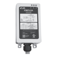
Designed for Marine, RV, HVAC, and commercial uses to reduce compressor in-rush current.

System Monitoring and Fault Response

Monitors voltage, current, startup, and integrity, providing diagnostic fault information via LED.

Product Specifications

Controller Type and Ratings

Semi-Conductor Soft-Start Motor Controller, Form 2, Bypassed; includes SCCR, voltage, and pollution degree.

Input and Output Electrical Details

Input 100-240 VAC with specific over/under voltage limits; output max 32A nominal, 40A over current.

Environmental and Physical Dimensions

Specifies ambient temperature, humidity, IP65 enclosure, and mounting dimensions.

Comparable Models and Standards

Manufacturer Cross-References

Lists comparable amperage models from Micro-Air, Network RV, Dometic, and Hyper Engineering.

Compliance and Test Results

Lists UL and CSA standards (60947-1, 60947-4-2), IP65 rating, and altitude limit.

LED Indicators and Fault Codes

LED Status Indicators

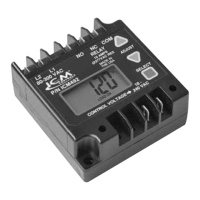
Defines LED colors for START (Green), RUN (Green), and FAULT (Red flashing) states.

Troubleshooting Fault Codes

Lists fault codes 1-5 with corresponding conditions like voltage, current, and frequency errors.

Wiring Diagrams

Residential A;C Wiring Diagram

General layout wiring diagram for connecting the soft start to residential air conditioning units.

RV & Marine A;C Wiring Diagram

General layout wiring diagram for connecting the soft start to RV and Marine air conditioning units.

Installation Instructions

Residential Installation Steps

Step-by-step guide for connecting ICM870 wires to residential compressor components.

RV & Marine Installation Steps

Step-by-step guide for connecting ICM870 wires to RV/Marine compressor components.

Model Selection and Load Data

Choosing the Correct ICM870 Model

Guidance on selecting ICM870-9A, -16A, or -32A based on compressor Rated Load Amps (RLA).

Average Load Conversion Chart

Chart providing average conversions for AC/Heat Pump tonnage, BTU, HP, and RLA.

Related product manuals