LIAF312
800.365.5525
7313 William Barry Blvd., North Syracuse, NY 13212
INSTALLATION INSTALLATION
Sostart
R S
C
OL
L2
L1
T2
Remove the Compressor
Run Winding Wire from T2
of the Contactor and Splice
to the ICM870 Brown Wire
NOTE (Step 2A)
Compressor
Contactor
Control
Voltage
Line
Voltage
Coil
T1
Compressor
Black
Blue
Brown
Splice
(Step 2B)
Red
Run
Cap
CH
Legend:
S = Start
C = Common
H = Hermetic
R = Run
OL = Overload Switch
!
!
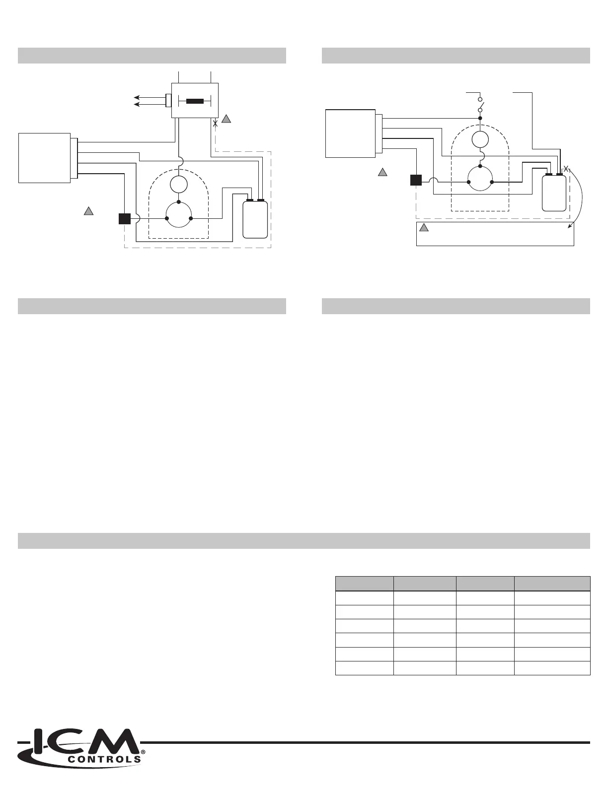
WIRING DIAGRAM (GENERAL LAYOUT) WIRING DIAGRAM (GENERAL LAYOUT)
RESIDENTIAL A/C
’s
RV & MARINE A/C
’s
Sostart
R S
C
OL
Compressor
Black
Blue
Brown
Splice
(Step 1B)
Red
Run
Cap
Legend:
S = Start
C = Common
H = Hermetic
R = Run
OL = Overload Switch
CH
!
NOTE Remove the Compressor Run Winding Wire from
Common (C) of the Run Capacitor and Splice to the Brown Wire of
the ICM870 So Start
!
Step 1A
WHICH MODEL DO I NEED?
For AC’s with a Compressor Rated Load Amps (RLA) of up to 9A
For AC’s with a Compressor Rated Load Amps (RLA) of 9.1-16A
For AC’s with a Compressor Rated Load Amps (RLA) of 16.1-32A
This chart reflects average conversions of Single-Phase Air Conditioning and
Heat Pump Tonnage, BTU’s, HP, and RLA. Please refer to you user manual
or service panel to determine your actual RLA before deciding which model
ICM870 you need.
Size BTU RLA ICM870 Model
1 Ton 12,000 6 9A
2 Ton 24,000 12 16A
3 Ton 36,000 16 16A
4 Ton 48,000 22 32A
5 Ton 60,000 26 32A
6 Ton 72,000 32 32A
Connect the ( > to the run capacitor
terminal (c/common/T2)
a) Disconnect factory installed compressor run wire from the
contactor terminal (T2/L2)
b) Splice the () > to the compressor
run wire previously disconnected in (Step 2A)
If there is a Start Capacitor and or PTCR already in place,
additional steps will be required to disconnect.
Connect the () > to the run capacitor
terminal (herm/hermetic/start)
Connect or splice the () > to the
contactor terminal (T1)
a) Disconnect factory installed compressor run wire from the
common run capacitor / L2 terminal
b) Splice the > to the factory installed
compressor run wire previously disconnected in step #1A.
If there is a Start Capacitor and or PTCR already in place,
additional steps will be required to disconnect them.
> to the run capacitor (c/common/L2)
terminal
Connect the > to the run capacitor
(herm/hermetic/start) terminal
Splice the > with the factory install
compressor Overload Switch wire (OL/L1)
Special attention should be made with respect to the termination of the eld wiring leads. When these leads are terminated at a
terminal, they shall terminate only at a terminal suitable for minimum 90°C wire.
 Loading...