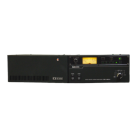
17. Put 2KL chassis back on your bench.
18. Maneuver the LPF unit behind the main board( orient the plugs thru the slots ) and
secure with 8 screws.
19. Re-seat this assembled unit into the 2KL chassis and install. Three bottom screws
(loosely) and one rear panel screw. Once all screws are inserted, then tighten securely.
20. Re-install J2 & J3.
21. Re-install J7 & J2 (on the main board).
22. YOU’RE NOT DONE YET
.. We need to fold down the front panel to have access to a
circuit trace, so remove the 2 screws on the bottom front & one on each side.
23. With the unit facing you, fold front panel down towards you. See two circuit
boards, 8446 & B447A. Notice a circuit board with wires soldered to it. (8447A). See a
PURPLE
wire soldered to the board ... follow this trace until you come to the first
connection off the trace.., with a knife, remove, cut or sever this connection point from
this trace.
24. Put the front panel back on. Adj ALC pot on rear panel as you would on the other
bands.
CONGRATULATIONS
. . YOU DID IT!
- _
SEE YOU ON 10 METERS.
Page 3 of 3
11-9-90 DV:vlm
(Source: Modification notes accompanying the Icom America IC-2KL 10/12m Modification Kit)

 Loading...