EasyManua.ls Logo

Icom 2KL User Manual

Icom 2KL
10 pages
To Next Page IconTo Next Page
Page #1 background imageLoading...
Page #1 background image
2KL – 10 METER MODIFICATION
1. Remove top cover ( 8 screws)
2. Turn unit upside down and remove 3 screws holding main unit to chassis and one more
on back side below "ant" port. Unit should be free from frame chassis.
3. Turn unit on side, with main unit facing up. On left hand side of main unit
disconnect J2 & J3, then maneuver the main unit out of chassis about 2 or 3 inches.
4. On bottom right of board disconnect J7. On left side see 4 resistors. Next to them
see 4 phono plugs. Disconnect J2 or bottom left one.
5. Remove 8 screws holding main board to filter unit ( They may have blue or green
colored loc-tite on them ).
6. Separate the two units and totally lift the LPF unit from chassis. TAKE CARE
...DON'T TEAR ANY CABLES.
7. SET THE 2KL CHASSIS ASIDE.
8. Look at the LPF unit ... Become familiar with design scheme ... Look at relays &
coils & caps ... notice empty spot (near ant conn). This is where the 10 meter
modification goes.
9. Remove 3 screws holding back cover plate. Remove plate cover.
10. We need to remove some parts that are in the way and some jumpers before installing
our parts. so refer to Fig 1 and remove in the following order( so none are missed )
1) Cap on component side
2) Cap on component side( silk screening may say C4 )
3) Coil on component side (silk screen may say L1)
4) Jumper on foil side (It is shorting one side of L1 to ground).
5) Jumper on component side.
** 6) REMOVE ANY CAPS
tacked on the foil side. There should be nothing on the foil side
but jumper(insulated) wires.
11. Now we can install our wires & parts. BUT FIRST
... REFER TO
FIG
2 and clear solder from the holes where the parts &
jumpers go. Let's do the jumper first. Open parts bag &
remove a white looking resistor. (its actually an insulated
jumper). Cut both leads off at the body and discard
body. On component side, install the two jumpers detained
in Fig 2 and by dashed lines(silk screening) on the board
itself. KEEP THEM FLUSH TO THE BOARD
... NOT BOWED !!
Page 1 of 3
11-9-90 DV:vlm
Question and Answer IconNeed help?

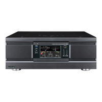
Do you have a question about the Icom 2KL and is the answer not in the manual?

Icom 2KL Specifications

General IconGeneral
TypeHF Linear Amplifier
RF output2000 W PEP
Driver power50-100 W
Input impedance50 Ohms
Output impedance50 Ohms
Input Power50-100 W
ModeSSB, CW, AM
Power Supply220 V AC
Frequency Range1.8-54 MHz

Summary

IC-2KL 10 Meter Modification Procedure

Disassembly and Unit Preparation

Steps for removing the unit, disconnecting cables, and preparing the chassis for modification.

LPF Unit Component Removal

Identifying and removing specific components and jumpers from the LPF unit as per instructions.

Jumper Installation

Installing the specified jumpers onto the LPF board, ensuring they are flush to the board.

Soldering and Wire Connections

Guidelines for clean soldering and connecting specific wires for the modification, referencing diagram details.

Component Installation

Installing the remaining specified components (relays, jumpers, coils, diodes, capacitors) onto the LPF board.

Final Checks and Reassembly

Performing final checks for cleanliness and correctness, then re-installing the LPF cover plate.

Unit Reassembly and Connector Re-installation

Re-installing the LPF unit into the chassis, securing it, and re-connecting cables.

Front Panel Circuit Trace Modification

Accessing the front panel to modify a specific circuit trace on the LED Display board.

Final Adjustments and Completion

Putting the front panel back on, adjusting the ALC pot, and acknowledging the modification's completion.

Notes on the IC-2KL 10/12m Modification

Initial Removal and Component Identification

Recommendations for removing the LPF unit and identifying specific components for removal (L31, C57, C58).

Soldering and Jumper Details

Discussion on desoldering challenges, the use of jumper components, and the location of hidden jumpers.

Wire Installation and Routing

Details on installing specific wires (N and G) and their routing paths on the board.

Trace Cutting and Final Notes

Instructions for cutting a trace on the LED Display board and final remarks on the modification's outcome.

10m Indicator LED Installation

Detailed steps for installing a 10-meter indicator LED on the front panel, including drilling and mounting.

Alternative Bandswitch Upgrade

Suggests a more involved upgrade using an 'E' version bandswitch for a factory look with multiple LEDs.

Related product manuals