2
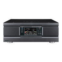
To install a 10m indicator LED, I pulled the meter switch knob off of the front panel and
removed the plastic face (six screws). Underneath was a black aluminum plate, which
covers up the E holes in the A version. I drilled a hole where the 24-28 MHz LED would
normally be. The I held the metal plate on the back of the plastic front plate, and
carefully (sing the metal plate as a template) drilled just far enough into the plastic
plate to remove the black paint on the back of the plastic plate, and just deep enough to
accommodate the end of a sub-miniature LED available from Radio Shack. The green matches
the ICOM green perfectly.
The little LED is inserted into the D7 (which is shown on the pictorial as D7(E)), with
the cathode toward the edge of the board. The short lead is the cathode.
Now, when the exciter is switched to either 24 or 28 MHz, the little green LED lights up,
if the 2KL is in the REMOTE position. When it is off, you can't even tell that there is a
LED installed there.
A better solution is to install an E version of the bandswitch, the front plastic plate
and the black aluminum plate that fits behind it, as well as three green LEDs. The front
panel with 24-28 silkscreened on it at the 10 Meter position will give the modified IC-
2KL a “factory” look.
(Source: W6SKC’s IC-2KL Modification Notes, April 1989)