C
Cynthia KramerJul 31, 2025
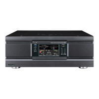
Why is the output power too low on my Icom Amplifier?
- TTaylor ScottJul 31, 2025
There could be several reasons for low output power: 1. Check that the antenna input and output are connected properly. 2. Ensure that the [ALC adj] is correctly adjusted. 3. Verify the linear amplifier circuit is turned ON by pushing [AMP/PROTECT] (the indicator should be green). 4. Make sure you've selected an antenna suitable for the operating frequency. 5. Tune the antenna manually by pushing [TUNER] for 2 seconds. 6. If the protection circuit activates and a band indicator blinks, stop the exciter’s transmission, then push [AMP/PROTECT] to deactivate the protection circuit.