4 - 4
4-3 MAIN UNIT ADJUSTMENT
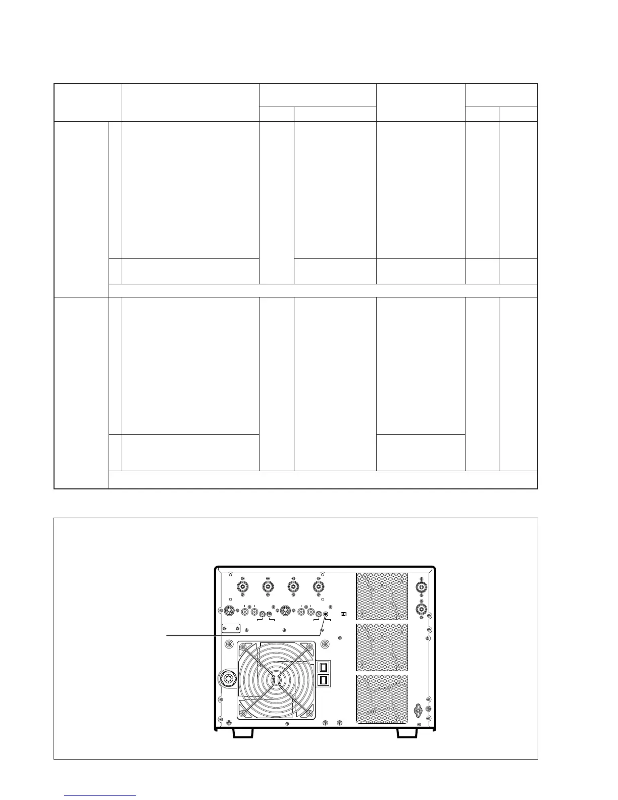
The TUNER BASIS VOLTAGE ADJUSTMENT needs the IC-736 as an exciter.
SWR
DETECTOR
CIRCUIT
TUNER
BASIS VOLT-
AGE
ADJUSTMENT
ADJUSTMENT ADJUSTMENT CONDITION
MEASUREMENT
VALUE
POINT
UNIT LOCATION UNIT ADJUST
1
2
1
2
• Input AC voltage : 200 V
• Pre-set R4, R6, R15 to 90˚ coun-
terclockwise
• Pre-set R5, R22 to center.
• Pre-set S3 to 5, and S4 to 4.
• [METER-1] : [P
O] scale
• Pre-set ALC adj1 to max. coun-
terclockwise, and then turn slow-
ly ALC adj1 to max. clockwise.
• Exciter frequency : 54.0 MHz
• Mode : RTTY
• RF power : minimum
• Transmitting
• [METER-2] : [SWR] scale
• Transmitting
• Disconnect J5 on the tuner unit of
IC-736, and then connect to J18
on the MAIN unit of IC-PW1.
• Connect [ANT1] connector of IC-
736 to [INPUT1] connector of IC-
PW1.
• Connect a 150 Ω dummy load to
[ANT1] connector of IC-PW1.
• Turn S5 to “SET”.
• Connect CP1 to ground.
• Push and hold [ANT], [ENT] and
[TUNER] switches of IC-736,
then turn IC-736 ON.
• Push [TUNER] key of IC-736.
Controller
IC-736
[METER-1]
[METER-2]
DISPLAY
400 W
Minimum value
Display of IC-736
shows “SET”.
Display of IC-736
shows “END”.
Exciter
FILTER
RF
power
volume
C73
Verify
• SWR detector circuit adjustment
• After adjustment, reset ALC adj1 to max. conterclockwise.
After adjustment, remove the jumper wire from CP1 and reset S5 to counter side.



 To Next Page