Do you have a question about the Icom IC-F1000S and is the answer not in the manual?
General technical characteristics of the transceivers.
Transmitter performance specifications like output power and deviation.
Receiver performance specifications like sensitivity and selectivity.
Visual identification of components on the main unit's top side.
Visual identification of components on the main unit's bottom side.
Steps to remove the front panel of the transceiver.
Steps to remove the main unit from the chassis.
Detailed description of the transceiver's receive signal path.
Detailed description of the transceiver's transmit signal path.
Description of the frequency synthesizer operation and components.
Diagram showing voltage distribution and power supply circuits.
Pin assignments and descriptions for the CPU.
Required equipment and connection setup for adjustments.
Procedure for adjusting frequency parameters using the utility.
Procedures for adjusting transmit power and modulation parameters.
Procedure for adjusting receiver sensitivity and squelch parameters.
List of mechanical parts for the chassis.
List of mechanical parts for the main unit.
List of mechanical parts for accessories.
Diagram showing the layout of components on the top side of the main unit PCB.
Diagram showing the layout of components on the bottom side of the main unit PCB.
Voltage distribution diagram for the main unit, part 1.
Voltage distribution diagram for the main unit, part 2.
Voltage distribution diagram for the main unit, part 3.
| Brand | Icom |
|---|---|
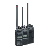
| Model | IC-F1000S |
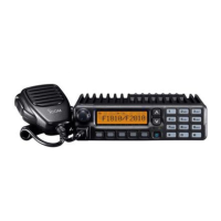
| Category | Transceiver |
| Language | English |