Do you have a question about the Icom IC-F320S and is the answer not in the manual?
Read all instructions carefully and completely before using the transceiver.
Manual contains important operating instructions for specific Icom transceivers.
Defines terms like Warning, Caution, and Note used throughout the manual.
Never connect to AC outlet or power source > 16V DC. Avoid cutting DC power cable.
Do not place where it hinders operation or causes injury. Keep away from children and liquids.
Use only the supplied microphone; others may cause damage due to different pin assignments.
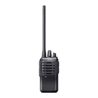
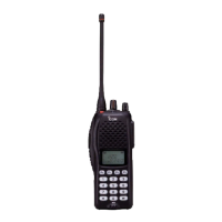
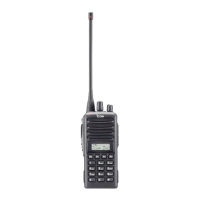
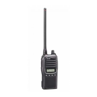
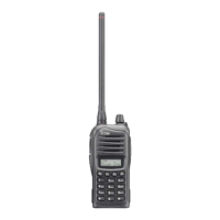
Identifies controls on the front of the transceiver, including keys, display, and connectors.
Explains the icons and alphanumeric display on the transceiver's screen.
Details how various functions can be assigned to programmable keys like P0-P3, ^, V.
Explains how to select output power and use the talk around feature for mobile-to-mobile communication.
Describes the use of Call keys (CAL A/B) for signaling and the Emergency key for distress calls.
Details selecting Tx code channels/numbers and performing DTMF transmissions.
Covers recalling/erasing ID codes and adjusting the backlight. Includes Attenuator and Trunking Group Switch.
Steps to turn the transceiver on, including passcode entry if applicable.
Explains how to select channels via non-bank, bank, or automatic scan types.
Guides on how to receive calls and transmit, including microphone usage and timing.
Discusses transmit inhibit functions, time-out timer, and penalty timer for transmission control.
Details selecting Tx code channels/numbers and performing DTMF transmissions.
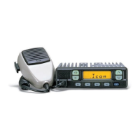
Illustrates how to connect antenna, microphone, speaker, and power cable to the rear panel.
Lists and describes the accessories included with the transceiver, like microphone, cables, and fuses.
Instructions for securely mounting the transceiver using the provided bracket and screws.
Steps for installing optional UT-96/UT-105 units into the transceiver.
Guide for installing the OPC-617 accessory cable to connect external terminals.
Advice on antenna selection, fuse replacement, and cleaning the transceiver.
Explains transceiver capability for SmarTrunk II and conventional channels using the optional UT-105.
Details features like placing/receiving calls and subscriber interactions within SmarTrunk II system.
Covers terminating calls, redialing, memory speed dialing, and programming speed dial numbers.
Explains system busy indications, dispatch call initiation, and receiving dispatch calls.
Instructions on initiating an emergency call and contacting the dealer for details.
Describes how the transceiver alerts for open channels and redials the last number.
Lists and describes optional external speakers (SP-5, SP-10) and microphones (HM-100T/TA, HM-100).
Details optional units like the UT-96 5-TONE UNIT and UT-105 Logic Board, plus the OPC-617 ACC CABLE.
| Brand | Icom |
|---|---|
| Model | IC-F320S |
| Category | Transceiver |
| Language | English |