ADJUSTMENT PROCEDURE
M CONNECTION
EQUIPMENT GRADE AND RANGE EQUIPMENT GRADE AND RANGE
Adjustment software
ADJ-M324
(Revision 1.0 or later)
Cloning cable OPC-478UC
Power supply
Voltage : 12.0 V
Current capacity : More than 10 A
RF power meter
(50
Ω
terminated)
Measuring range : 0.1–30 W
Frequency range : 100–300 MHz
SWR : Less than 1.2 : 1
Frequency counter
Range : 0.1–300 MHz
Accuracy : ±1 ppm or better
Input level : Less than 1 mW
Modulation
Analyzer
Frequency range : 30–300 MHz
Measuring range : 0 to ±10 kHz
Standard signal
generator (SSG)
Frequency range : 0.1–300 MHz
Output level : –20 dBµ to 90 dBµ
(–127 to –17 dBm)
AC millivoltmeter Measuring range : 10 mV to 10 V
Oscilloscope
Frequency range : DC–20 MHz
Measuring range : 0.01–20 V
Attenuator
Attenuation : 40 dB
Capacity : More than 30 W
Audio generator
(AG)
Frequency range : 300–3000 Hz
Output level : 1–500 mV
External speaker
Input impedance : 4
Ω
Capacity : More than 10 W
M REQUIRED EQUIPMENTS
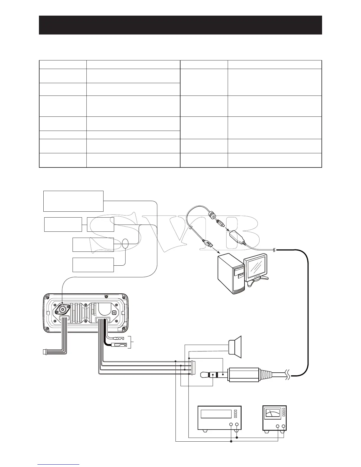
1 PREPARATION
+−
AC
MILLIVOLTMETER
(10 mV to 10 V)
AUDIO GENERATOR
(300–3000 Hz/1–500 mV)
+−
TRANSCEIVER
OPC-478UC
PC
FM
deviation meter
to the antenna connector
Attenuator
40 dB
RF power meter
0.1–30 W/50 Ω
Frequency
counter
Standard signal generator
–20 to 90 dBµ
(–127 dBm to –17 dBm)
12.0 V power supply
(ICF3)
(GND)
(SP+)
“Orange”
“Blue”
“Gray”
“Black”
(SP-)
EXT. SPEAKER
(10 W/4 Ω)
+
−
(Additional page)
July 2013
 Loading...