DISASSEMBLY INSTRUCTION
BE CAREFUL about the fl at cable and connector when
separating the front panel from the chassis assmbly.
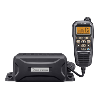
1. Removing the FRONT UNIT
1) Remove 6 screws from the rear.
2) Disconnect the fl at cable and inline cable from the
LOGIC UNIT.
3) Separate the front panel from the chassis assembly.
2. Removing the MAIN UNIT
1) Remove 6 screws from the rear.
2) Remove the case from the chassis.
4) Remove 4 screws from the LOGIC UNIT.
5) Remove the LOGIC UNIT.
3) Disconnect the inline cable from the bottom of MAIN
UNIT.
4) Unsolder 2 points at the power supply cable.
(Continued on next page.)
 Loading...