81
11
CONNECTIONS
■ Connections
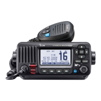
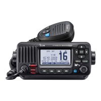
L The IC-M510BB is used as an example.
Front panel: Rear panel:
1 2 3
4
5
6
7
8
9
1COMMAND MICROPHONE JACK
Connects the supplied or optional
command microphone.
L Only the IC-M510BB has [MIC3] jack.
2NMEA 2000™ CONNECTOR
Connects to an NMEA network.
3GPS ANTENNA CONNECTOR
Connects to the supplied or optional
GPS antenna.
NOTE: Be sure the GPS antenna is
positioned where it has a clear view
to receive signals from satellites, and
pad supplied with the antenna.
4ANTENNA CONNECTOR
Connects to a marine VHF antenna with
a PL-259 connector.
A key element in the performance of any
communication system is the antenna.
CAUTION: DO NOT transmit without
an antenna.
5NMEA IN/OUT LEADS
Yellow: Listener A (Data-H), Data In (+)
Green: Listener B (Data-L), Data In (–)
Connect to the NMEA output lines of
a GPS receiver or an AIS device for
position data.
• NMEA 0183 (ver. 2.0 or later) sentence
format RMC, GGA, GNS, or GLL
GPS receivers.
• The GPS sentences input from this
connector are given priority over the
receiver.
• The AIS information through the AIS
device inputs as VDM sentence.
L
• The external VDM sentence takes
precedence over others.
White: Talker A (Data-H), Data Out (+)
Brown: Talker B (Data-L), Data Out (–)
Connect to NMEA 0183 input lines of a
navigation equipment.
• An NMEA 0183 (ver. 2.0 or later)
navigation equipment is required.
• The GPS outputs RMC format sentences.
• The AIS information through the
NMEA2000 device and the internal AIS
receiver outputs as VDM sentences.
FELLECS-TECH | inbox@fellecs-tech.com | www.fellecs-tech.com