Do you have a question about the Icom IC-M402 and is the answer not in the manual?
Lists critical warnings for operating and connecting the transceiver to prevent damage or injury.
Details general parameters like frequency, mode, power supply, dimensions, and weight.
Lists transmitter metrics including output power, modulation, and frequency deviation.
Outlines receiver metrics such as sensitivity, selectivity, and intermodulation rejection.
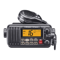
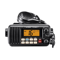
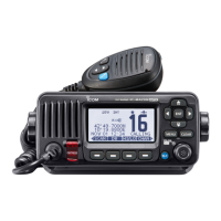
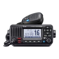
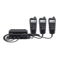
Provides visual identification of components on the main and front units of the IC-M402.
Details the steps for disassembling the transceiver case and removing the main unit.
Lists required test equipment and connection diagrams for adjustments.
Details procedures for adjusting PLL lock voltage and reference frequency.
Covers adjustments for transmitter output power and receiver sensitivity/squelch.
| Type | Marine VHF Transceiver |
|---|---|
| Weight | 1.1 kg |
| Waterproof Rating | IPX7 |
| Display Type | LCD |
| Output Power | 25W |
| Channels | USA, INT, CAN channels |
| Power Supply | 13.8V DC |
| Modulation | FM |