EasyManua.ls Logo

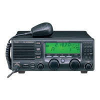
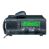
Icom IC-M700PRO - Service Manual

Icom IC-M700PRO
73 pages
Print Icon
To Next Page IconTo Next Page
Loading...

Table of Contents

Other manuals for Icom IC-M700PRO

Questions and Answers

  • T
    Tracey ColeSep 10, 2025
    Why is the received audio unclear or distorted on my Icom Telephone?
    • J
      Jose WaltersSep 10, 2025
      If the received audio on your Icom Telephone is unclear or distorted: * Ensure the correct operating mode is selected by pushing [MODE]. * If receiving a strong signal, activate the AGC function by pushing [AGC]. * Turn OFF the noise blanker by pushing [NB] if it's ON while receiving a strong signal. * Adjust the [CLARITY] control to achieve proper audio output.
  • M
    Michele JonesSep 12, 2025
    Why is my Icom Telephone sensitivity too low?
    • J
      James ChambersSep 12, 2025
      If the sensitivity of your Icom Telephone is too low, and only strong signals are audible, it could be caused by: * The antenna not being properly matched to the operating frequency. Push [TUNE] to tune using the antenna tuner, or select 'automatic tuning' in the set mode when using an optional AT-130. * The wrong tuner being selected in the set mode. Set the proper tuner for the connected tuner. * The squelch being set too deep. Adjust the squelch to the proper level.
  • J
    Jeff RyanSep 14, 2025
    What causes unclear or distorted transmit signal on Icom Telephone?
    • C
      Carolyn FordSep 14, 2025
      If your transmit signal on the Icom Telephone is unclear or distorted: * Ensure that the correct operation mode is selected by pushing [MODE]. * Make sure you are speaking into the microphone naturally and not holding it too close to your mouth.
  • S
    sheila23Sep 16, 2025
    What to do if all indicators appear on Icom Telephone?
    • F
      fchapmanSep 16, 2025
      If all indicators appear on your Icom Telephone and the channel number cannot be read, set to the proper display contrast, because the highest contrast is selected in the set mode.

Summary

Section 1 Specifications

General Specifications

Covers frequency coverage, mode, channels, impedance, temperature, power, dimensions, weight, and connectors.

Transmitter Specifications

Details output power, spurious emissions, carrier suppression, and microphone impedance.

Receiver Specifications

Details receiver sensitivity, spurious response, audio output, and impedance.

Section 3 Circuit Description

3-1 Receiver Circuits

Detailed description of the receiver circuit, including RF filters and mixers.

3-2 Transmitter Circuits

Description of the transmitter circuits, including modulation and power amplification.

3-3 PLL Circuit

Explanation of the Phase-Locked Loop (PLL) circuit for frequency generation.

Section 4 Adjustment Procedures

4-3 Transmitter Adjustments

Procedures for adjusting transmitter parameters like idling current and output power.

Section 8 Board Layouts

Section 9 Board Diagram

Section 10 Voltage Diagram

Icom IC-M700PRO Specifications

General IconGeneral
Tuning Steps10 Hz
TypeMarine SSB Transceiver
Output Power150 W PEP
Power Supply13.8 V DC
Current ConsumptionReceive: 1.5 A

Related product manuals