3. Timehowmanysecondsittakesthesmallestdialonthegas NOTE:Ifmeterusesa2cubicfootdial,divideresults(seconds)by
metertomakeonecompleterevolution.RefertoExample. two.
4. Relightallappliancesandensureallpilotsareoperating.
!i!i!i!!ii !i!i ilii!iiii!!
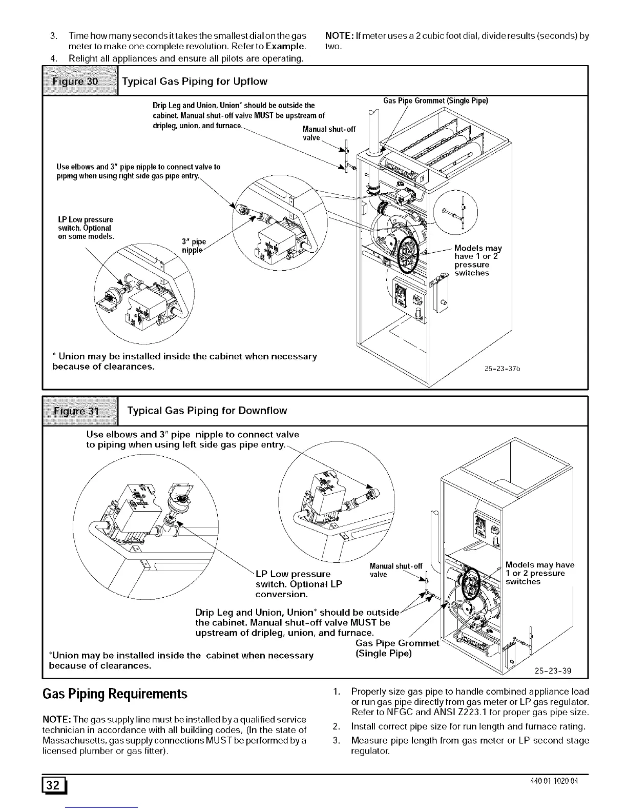
Typica,GasPipiog,orU .ow
Drip Legand Union,Union* shouldbeoutsidethe GasPipe Grommet(SinglePipe)
cabinet.Manualshut-off valveMUSTbe upstreamof "_ _Y / _//_
dripleg,union, andfurnace. Manualshut-off
Useelbows and3" pipenippleto connectvalveto _
on some models. . / \ /_ _ \ /
have 1 or 2
I Typical Gas Piping for Downflow
Use elbows and 3" pipe nipple to connect valve
to piping when using left side gas pipe
LP Low pressure
switch. Optional LP
conversion.
Manualshut- off
valve
Drip Leg and Union, Union* should be
the cabinet. Manual shut-off valve MUST be
upstream of dripleg, union, and furnace.
Gas Pipe Grommet
*Union may be installed inside the cabinet when necessary (Single Pipe)
because of clearances.
4odels may have
1 or 2 pressure
switches
25-23-39
Gas Piping Requirements
NOTE: The gas supply line must be installed bya qualified service
technician in accordance with all building codes, (In the state of
Massachusetts, gas supply connections MUST be performed by a
licensed plumber or gas fitter).
1. Properly size gas pipe to handle combined appliance load
or run gas pipe directly from gas meter or LP gas regulator.
Refer to NFGC and ANSI Z223.1 for proper gas pipe size.
2. Install correct pipe size for run length and furnace rating.
3. Measure pipe length from gas meter or LP second stage
regulator.
[_1 440 01 1020 04