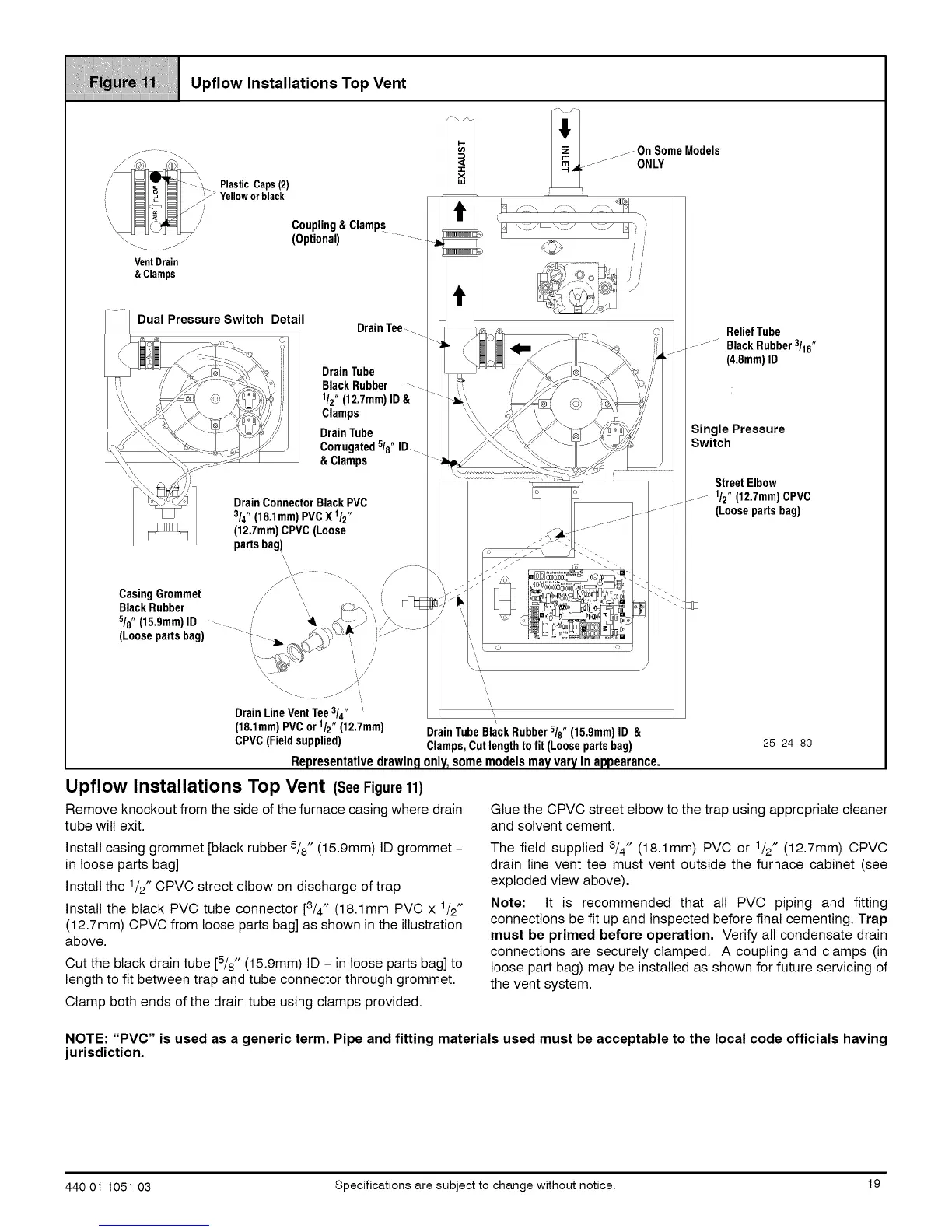
Upflow Installations Top Vent
VentDrain
& Clamps
Coupling&Clamps
(Optional)
Dual Pressure Switch Detail
DrainTee....
DrainTube
BlackRubber
1/2" (12,7mm)ID &
Clamps
DrainTube
Corrugated5/8"ID....
&Clamps
DrainConnectorBlack PVC
3/4" (18,1mm)PVCX 1/2"
(12,7mm)CPVC (Loose
partsbag)
CasingGrommet //
Black Rubber /
5/8"(15,9mm)ID - i"
(Loosepartsbag)
-_ s ¸
......On
SomeModels
...............ONLY
_ ==,,,,D % i
..... _r_ --, l_--_ _
\ <_, ,,7
.j-
. j-----
', i o o
DrainLineVentTee3/4" " ",,
(18.1mm)PVCor1/2"(12.7mm) DrainTubeBlackRubber/8 (15.9mm)ID &
CPVC(Fieldsupplied) Clamps,Cutlengthtofit (Loosepartsbag)
Representativedrawingonly_somemodelsmayvaryinappearance.
Upflow Installations Top Vent (SeeFigure11)
Remove knockout from the side of the furnace casing where drain
tube will exit.
Install casing grommet [black rubber 518" (15.9mm) ID grommet-
in loose parts bag]
Install the 1/2" CPVC street elbow on discharge of trap
Install the black PVC tube connector [3/4" (18.1mm PVC x 1/2"
(12.7mm) CPVC from loose parts bag] as shown in the illustration
above.
Cut the black drain tube [5/8" (15.9mm) ID -in loose parts bag] to
length to fit between trap and tube connector through grommet.
Clamp both ends of the drain tube using clamps provided.
ReliefTube
..............Black Rubber3/16"
(4.8mm)ID
Single Pressure
Switch
Street Elbow
......... 1/2" (12.7mm) CPVC
(Loose parts bag)
25-24-80
Glue the CPVC street elbow to the trap using appropriate cleaner
and solvent cement.
The field supplied 3/4" (18.1mm) PVC or 1/2" (12.7mm) CPVC
drain line vent tee must vent outside the furnace cabinet (see
exploded view above).
Note: It is recommended that all PVC piping and fitting
connections be fit up and inspected before final cementing. Trap
must be primed before operation. Verify all condensate drain
connections are securely clamped. A coupling and clamps (in
loose part bag) may be installed as shown for future servicing of
the vent system.
NOTE: "PVC" is used as a generic term. Pipe and fitting materials used must be acceptable to the local code officials having
jurisdiction.
440 01 1051 03 Specifications are subject to change without notice. 19