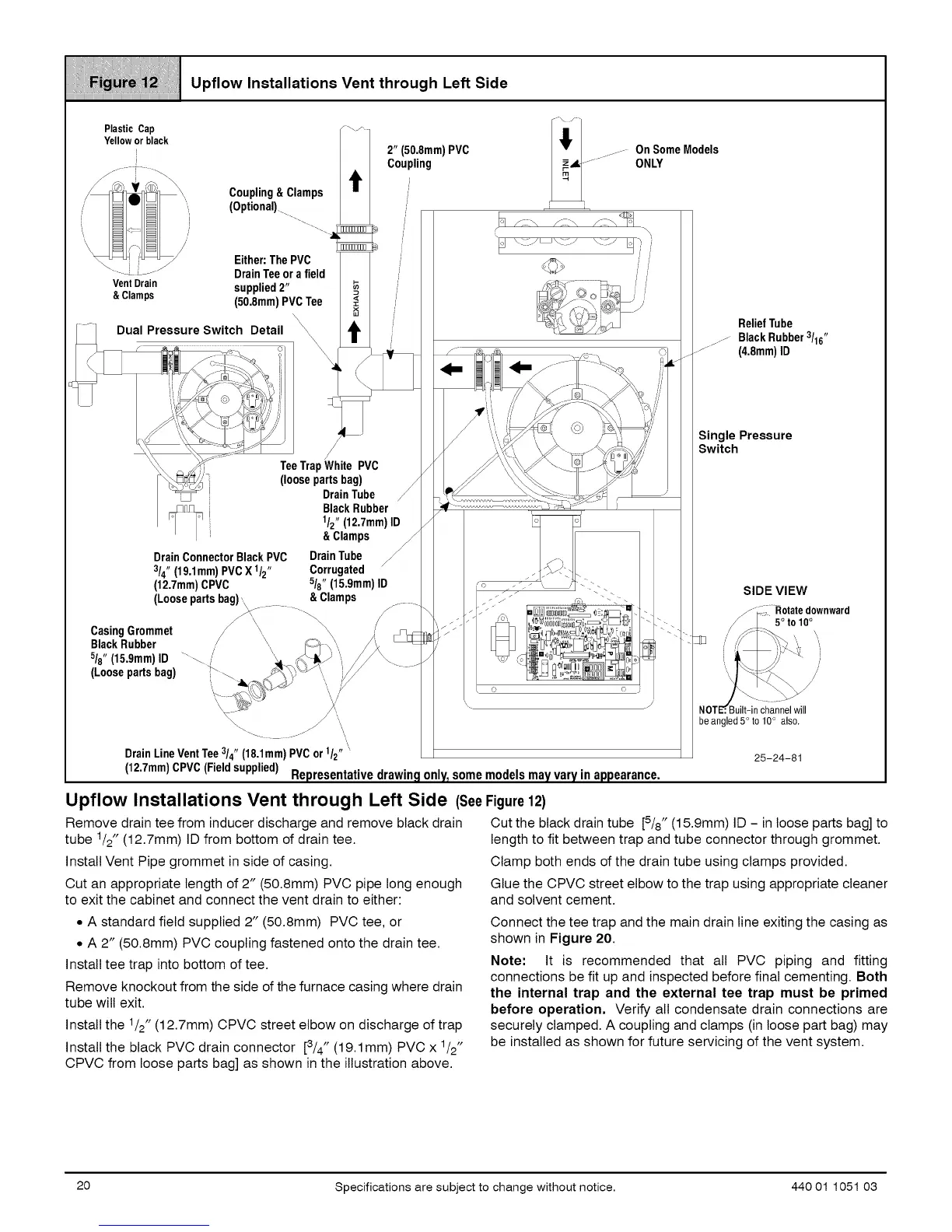
Upflow Installations Vent through Left Side
Plastic Cap
Yelloworblack
J
Coupling&Clamps
(Optional).
VentDrain
& Clamps
essure Switch Detail
Either:ThePVC
DrainTeeorafield
supplied2"
(50.8mm)PVCTee
\
TeeTrapWhite PVC
(loosepartsbag)
DrainTube
DrainConnectorBlackPVC
3/4"(19,1mm)PVCX 1/2"
(12,7mm)CPVC
Black Rubber
1/2"(12,7mm)ID
& Clamps
DrainTube
Corrugated
5/8"(15,9mm)ID
2" (50,8mm)PVC
Coupling
.....OnSomeModels
..... ---
ONLY
i i
/;\
&Clamps
/
• q r
. ]_J.' -.
ReliefTube
.....Black Rubber3/16"
(4.8mm)ID
Single Pressure
Switch
SIDE VIEW
(Loosepartsbag),,\.....
,_\\ _\\
CasingGrommet / \,
BlackRubber --. // \,\ .__- ',
5/8"(15,9mm)ID _ / '_ _ _-"
(Loosepartsbag) _ _ "_\_"_',,,,,
.... ,,
DrainLineVentTee3/4" (18,1mm)PVCor1/2""
(12.7mm)CPVC(Fieldsupplied)
\
0 o j
Representativedrawingonly_somemodelsmayvaryinappearance.
Rotatedownward
5° to 100
]uilt-in channelwill
be angled5° to 10° also.
25-24-81
Upflow Installations Vent through Left Side (SeeFigure12)
Remove drain tee from inducer discharge and remove black drain Cut the black drain tube [5/8" (15.9mm) ID - in loose parts bag] to
tube 1/2" (12.7mm) ID from bottom of drain tee. length to fit between trap and tube connector through grommet.
Install Vent Pipe grommet in side of casing. Clamp both ends of the drain tube using clamps provided.
Cut an appropriate length of 2" (50.8mm) PVC pipe long enough
to exit the cabinet and connect the vent drain to either:
Glue the CPVC street elbow to the trap using appropriate cleaner
and solvent cement.
• A standard field supplied 2" (50.8mm) PVC tee, or
• A 2" (50.8mm) PVC coupling fastened onto the drain tee.
Install tee trap into bottom of tee.
Remove knockout from the side of the furnace casing where drain
tube will exit.
Install the 1/2" (12.7mm) CPVC street elbow on discharge of trap
Install the black PVC drain connector [3/4" (19.1mm) PVC x 1/2"
CPVC from loose parts bag] as shown in the illustration above.
Connect the tee trap and the main drain line exiting the casing as
shown in Figure 20.
Note: It is recommended that all PVC piping and fitting
connections be fit up and inspected before final cementing. Both
the internal trap and the external tee trap must be primed
before operation, Verify all condensate drain connections are
securely clamped. A coupling and clamps (in loose part bag) may
be installed as shown for future servicing of the vent system.
20 Specifications are subject to change without notice. 440 01 1051 03