Downflow Left-Side Vent and Trap
j Plastic Cap
J Yellow or black
Coupling&Clamps
(Optional)\
VentDrain
&Clamps Either:The PVC
DrainTeeora field
supplied2"
(50.8mm)PV_Tee
Single Pressure Switch Detail \\
2" (50.8mm)PVC
Coupling
/ DrainTube
/ / BlackRubber1/2"
// (12.7mm)ID&Clamps
/
/
Dual Pressure Switch
PartsBag)
WARNING
MoveCapsto
topoftrap
DrainTubeBlack,5/8"(15.9mm)ID
CorrugatedCutatstraightsection {_i _ _-_ /_-_/._ _
\ J
I
i.......
...............A_,_,_,,_ _,............ BarbedCoupling1/2"(12.7mm)
OD(loosepartsbag)
Leaveroomforclamp _ CutHere
Representativedrawing only_some modelsmay vary in appearance.
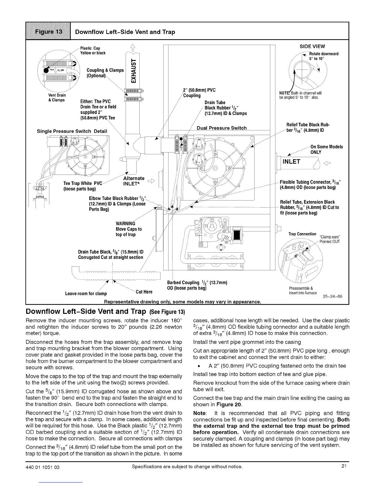
Downflow Left-Side Vent and Trap (SeeFigure13)
Remove the inducer mounting screws, rotate the inducer 180 °
and retighten the inducer screws to 20" pounds (2.26 newton
meter) torque.
Disconnect the hoses from the trap assembly, and remove trap
and trap mounting bracket from the blower compartment. Using
cover plate and gasket provided in the loose parts bag, cover the
hole from the burner compartment to the blower compartment and
secure with screws.
Move the caps to the top of the trap and mount the trap externally
to the left side of the unit using the two(2) screws provided.
Cut the 5/8" (15.9mm) ID corrugated hose as shown above and
fasten the 90° bend end to the trap and fasten the straight end to
the transition drain. Secure both connections with clamps.
Reconnect the 1/2" (12.7mm) ID drain hose from the vent drain to
the trap and secure with a clamp. Insome cases, additional length
will be required for this hose. Use the Black plastic 1/2" (12.7mm)
OD barbed coupling and a suitable section of 1/2" (12.7mm) ID
hose to make the connection. Secure all connections with clamps
Connect the 3/16" (4.8mm) ID relief tube from the small port on the
trap to the top port of the transition as shown in the picture. In some
SIDE VIEW
__[ Rotatedownward
.L 5°to10°
\
,//% .....
NOT_B. uilt-in channel will
be angled 5°to 10° also.
ReliefTubeBlackRub-
...._ber 3/16" (4.8mm)ID
.....OnSomeModels
,,Lj jj ONLY
INLET _,.
Flexible TubingConnector, 3/16"
(4.8mm)OD (loosepartsbag)
ReliefTube,ExtensionBlack
.......Rubber,3/16" (4.8mm)IDCutto
fit (loosepartsbag)
TrapConnection
"Clampears"
PointedOUT
Preassemble&
insertinto furnace
25-24-69
cases, additional hose length will be needed. Use the clear plastic
3/16" (4.8mm) OD flexible tubing connector and a suitable length
of extra 3/16" (4.8mm) ID hose to make this connection.
Install the vent pipe grommet into the casing
Cut an appropriate length of 2" (50.8mm) PVC pipe long, enough
to exit the cabinet and connect the vent drain to either:
• A 2" (50.8mm) PVC coupling fastened onto the drain tee
Install tee trap into bottom section of tee and glue pipe.
Remove knockout from the side of the furnace casing where drain
tube will exit.
Connect the tee trap and the main drain line exiting the casing as
shown in Figure 20.
Note: It is recommended that all PVC piping and fitting
connections be fit up and inspected before final cementing. Both
the external trap and the external tee trap must be primed
before operation, Verify all condensate drain connections are
securely clamped. A coupling and clamps (in loose part bag) may
be installed as shown for future servicing of the vent system.
440 01 1051 03 Specifications are subject to change without notice. 21
 Loading...