Downflow Right-Side Vent and Trap
j Plastic Cap
f- ".... _ J Yellowor black
VentDrain
& Clamps
SIDE VIEW
"-I-_ Rotatedownward
_J_ 5° to 10°
i, :¢_ _ /,
NOT_J n_e_
be angled5°to 10" also.
Single Pressure Switch Detail
Dr
5/8
ElbowTube BlackRubber
1/2"(12.7mm)ID &Clamps
(LoosePartsBag)
,\
Dual Pressure'Switch
BarbedCoupling
1/2"(12.7mm)OD
(LoosePartsBag)
]ir
' i
TubeCorrugatedBlack,
15.9mm)ID &Clamps
DrainConnectorBla(
PVC3/4"(19.1mm)
PVCX 1/?. (12.7mm)
CPVC(Looseparts
bag)
\
/
//////
.c
TrapConnection
"Clampears"
PointedOUT
ReliefTube
BlackRubber
/16"(4.8mm)ID
DrainHose /- _
BlackRubber| |
1/2" (12.7mm)I_
Cutto Fit&
Clamps
OnSome
Models
ONLYJ
Preassemble &
insert intofurnace
Coupling&Clamps
.(Optional)
,/
/ 2"(50.8mm)PVC
Coupling
Either:ThePVC
DrainTeeorafield
supplied2"
(50.8mm)PVCTee
TeeTrapWhitePVC
(loosepartsbag)
WARNING
\\
_ DrainTube)BlackRubber,5/8"
(15.9mm)IDCuttofit &Clamps
(loose partsbag)
25-24-69b
Representativedrawing only_some models may vary in appearance.
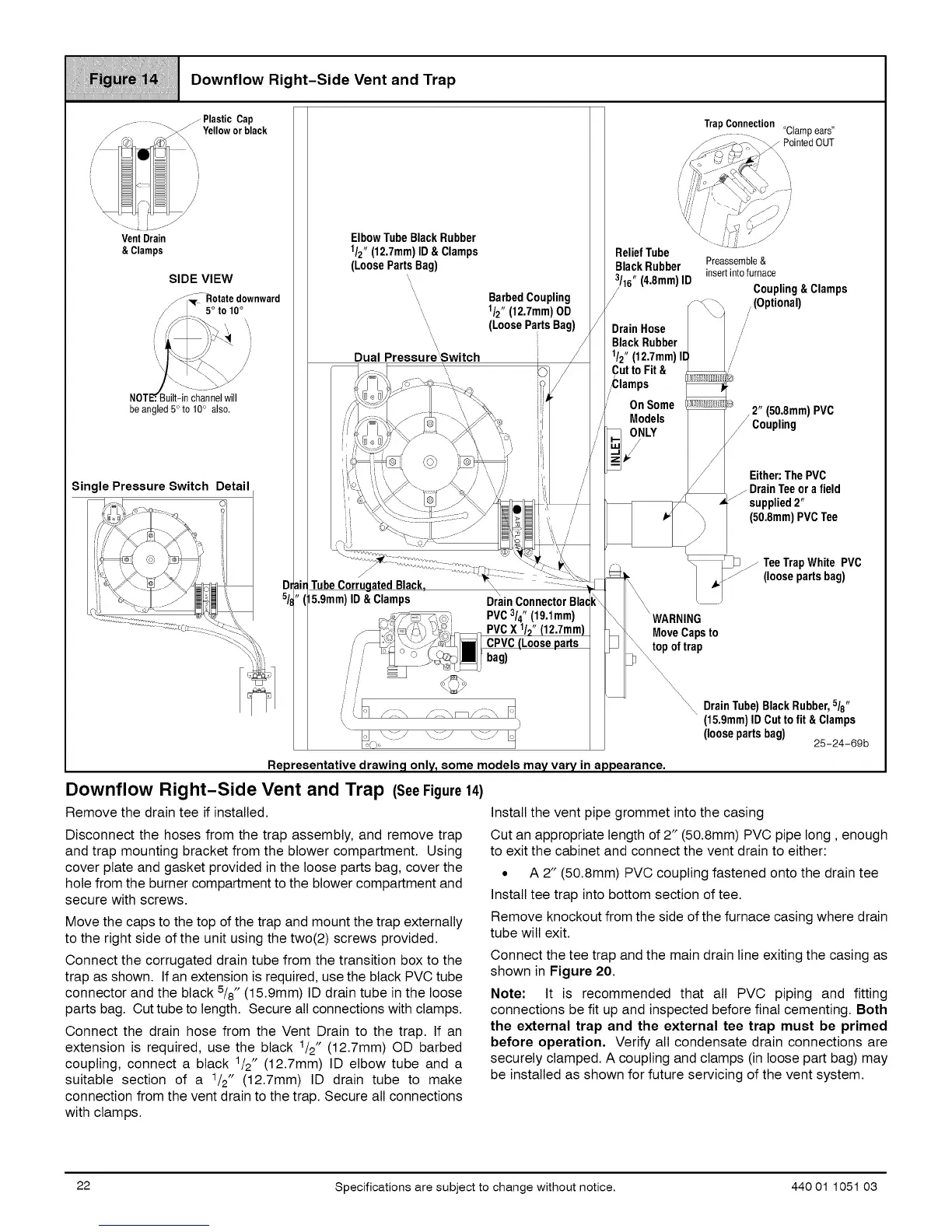
Downflow Right-Side Vent and Trap (SeeFigure14)
Remove the drain tee if installed.
Disconnect the hoses from the trap assembly, and remove trap
and trap mounting bracket from the blower compartment. Using
cover plate and gasket provided in the loose parts bag, cover the
hole from the burner compartment to the blower compartment and
secure with screws.
Move the caps to the top of the trap and mount the trap externally
to the right side of the unit using the two(2) screws provided.
Connect the corrugated drain tube from the transition box to the
trap as shown. If an extension isrequired, use the black PVC tube
connector and the black 5/8" (15.9mm) ID drain tube inthe loose
parts bag. Cut tube to length. Secure all connections with clamps.
Connect the drain hose from the Vent Drain to the trap. If an
extension is required, use the black 1/2" (12.7mm) OD barbed
coupling, connect a black 1/2" (12.7mm) ID elbow tube and a
suitable section of a 1/2" (12.7mm) ID drain tube to make
connection from the vent drain to the trap. Secure all connections
with clamps.
Install the vent pipe grommet into the casing
Cut an appropriate length of 2" (50.8mm) PVC pipe long, enough
to exit the cabinet and connect the vent drain to either:
• A 2" (50.8mm) PVC coupling fastened onto the drain tee
Install tee trap into bottom section of tee.
Remove knockout from the side of the furnace casing where drain
tube will exit.
Connect the tee trap and the main drain line exiting the casing as
shown in Figure 20.
Note: It is recommended that all PVC piping and fitting
connections be fit up and inspected before final cementing. Both
the external trap and the external tee trap must be primed
before operation, Verify all condensate drain connections are
securely clamped. A coupling and clamps (in loose part bag) may
be installed as shown for future servicing of the vent system.
22 Specifications are subject to change without notice. 440 01 1051 03
 Loading...