Concentric Termination
ConcentricVentTermination- Kit#
NAHAO01CV& NAHAO02CV
For Concentric Vent Termination information call 931.270.4100
with the complete model and serial number of the furnace.
Refer to Special Venting Requirements for Installations in Canada
in the Vent and Combustion Air Connections Section.
These kits are for vertical or horizontal termination of the
combustion air inlet and the exhaust vent pipes on Category iV
gas-fired condensing furnaces. The NAHA001CV kit can be used
for 3" (76.2mm) diameter pipe systems. The NAHA002CV kit can
be used for 2"(50.8mm) diameter pipe system. Refer to Table 4
for the correct pipe size for the furnace. Both the combustion air
inlet and the exhaust vent pipes must attach to the termination kit.
The termination kit must terminate outside the structure and must
be installed per the instructions outlined below for vertical or
horizontal termination. Vertical termination is preferred. Field
supplied pipe and fittings are required to complete the installation.
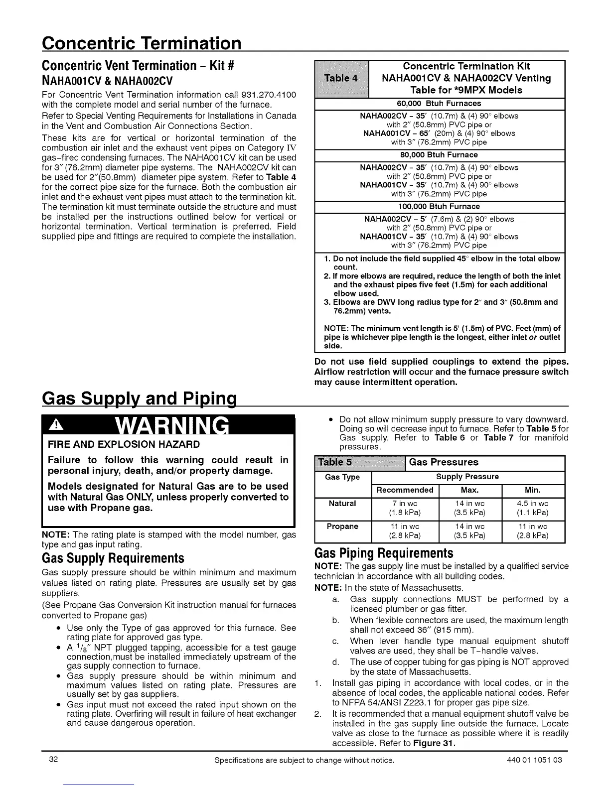
t;;' : Concentric Termination Kit
_ NAHA001CV & NAHA002CV Venting
Table for *9MPX Models
60,000 Btuh Furnaces
NAHAOO2CV- 35' (10.7m) & (4) 90° elbows
with 2" (50.8mm) PVC pipe or
NAHAOOICV- 65' (20m)& (4) 90° elbows
with 3" (76.2mm) PVC pipe
80,000 Btuh Furnace
NAHAOO2CV- 35' (10.7m) & (4) 90° elbows
with 2" (50.8mm) PVC pipe or
NAHAOOICV- 35' (10.7m) & (4) 90° elbows
with 3" (76.2mm) PVC pipe
100,000Btuh Furnace
NAHAOO2CV- 5' (7.6m) & (2) 90° elbows
with 2" (50.8mm) PVC pipe or
NAHAOOICV- 35' (10.7m) & (4) 90° elbows
with 3" (76.2mm) PVC pipe
1. Do not include the field supplied 45 ° elbow in the total elbow
count.
2, If more elbows are required, reduce the length of both the inlet
and the exhaust pipes five feet (1,5m) for each additional
elbow used.
3, Elbows are DWV long radius type for 2" and 3" (50,8mm and
76,2mm) vents,
NOTE: The minimum vent length is 5' (1.5m) of PVC. Feet (mm) of
pipe is whichever pipe length is the longest, either inlet or outlet
side.
Gas Supply and Piping
FIRE AND EXPLOSION HAZARD
Failure to follow this warning could result in
personal injury, death, and/or property damage.
Models designated for Natural Gas are to be used
with Natural Gas ONLY, unless properly converted to
use with Propane gas.
NOTE: The rating plate is stamped with the model number, gas
type and gas input rating.
Gas SupplyRequirements
Gas supply pressure should be within minimum and maximum
values listed on rating plate. Pressures are usually set by gas
suppliers.
(See Propane Gas Conversion Kit instruction manual for furnaces
converted to Propane gas)
• Use only the Type of gas approved for this furnace. See
rating plate for approved gas type.
• A 1/8" NPT plugged tapping, accessible for a test gauge
connection,must be installed immediately upstream of the
gas supply connection to furnace.
• Gas supply pressure should be within minimum and
maximum values listed on rating plate. Pressures are
usually set by gas suppliers.
• Gas input must not exceed the rated input shown on the
rating plate. Overfiring will result in failure of heat exchanger
and cause dangerous operation.
Do not use field supplied couplings to extend the pipes.
Airflow restriction will occur and the furnace pressure switch
may cause intermittent operation.
Do not allow minimum supply pressure to vary downward.
Doing so wilt decrease input to furnace. Refer to Table 5 for
Gas supply. Refer to Table 6 or Table 7 for manifold
pressures.
GasPressures
Gas Type Supply Pressure
Max.
14 in wc
(3.5 kPa)
14 in wc
(3.5 kPa)
Recommended Min.
Natural 7 in wc 4.5 in wc
(1.8 kPa) (1.1 kPa)
Propane 11 in wc 11 in wc
(2.8 kPa) (2.8 kPa)
Gas Piping Requirements
NOTE: The gas supply line must be installed by a qualified service
technician in accordance with all building codes.
NOTE: In the state of Massachusetts.
a. Gas supply connections MUST be performed by a
licensed plumber or gas fitter.
b. When flexible connectors are used, the maximum length
shall not exceed 36" (915 mm).
c. When lever handle type manual equipment shutoff
valves are used, they shall be T-handle valves.
d. The use of copper tubing for gas piping is NOT approved
by the state of Massachusetts.
1. Install gas piping in accordance with local codes, or in the
absence of local codes, the applicable national codes. Refer
to NFPA 54/ANSI Z223.1 for proper gas pipe size.
2. It is recommended that a manual equipment shutoff valve be
installed in the gas supply line outside the furnace. Locate
valve as close to the furnace as possible where it is readily
accessible. Refer to Figure 31.
32 Specifications are subject to change without notice. 440 01 1051 03
 Loading...