3. Use black iron or steel pipe and fittings or other pipe approved
by local code.
4. Use pipe thread compound which is resistant to natural and
Propane gases.
5. Use ground joint unions and install a drip leg no less than 3"
(76.2mm) long to trap dirt and moisture before it can enter gas
control valve inside furnace.
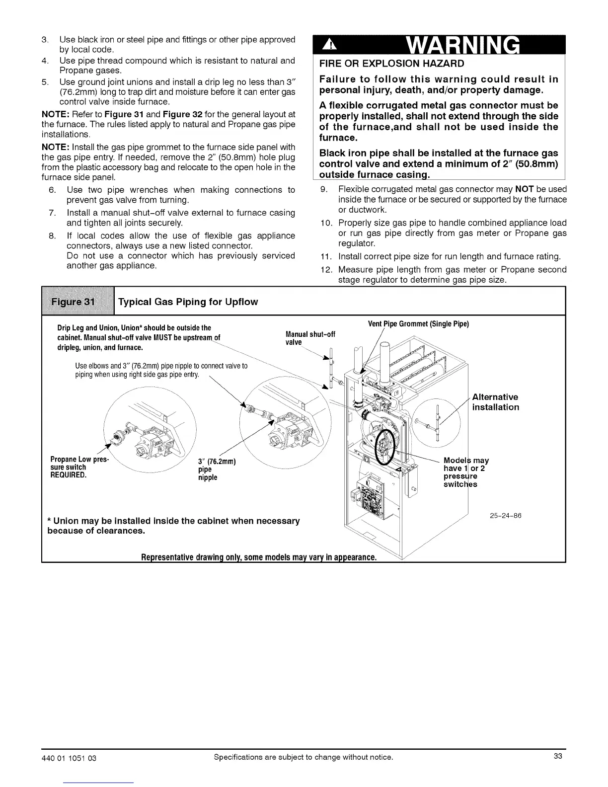
NOTE: Refer to Figure 31 and Figure 32 for the general layout at
the furnace. The rules listed apply to natural and Propane gas pipe
installations.
NOTE: Install the gas pipe grommet to the furnace side panel with
the gas pipe entry. If needed, remove the 2" (50.8mm) hole plug
from the plastic accessory bag and relocate to the open hole in the
furnace side panel.
6. Use two pipe wrenches when making connections to
prevent gas valve from turning.
7. Install a manual shut-off valve external to furnace casing
and tighten all joints securely.
8. If local codes allow the use of flexible gas appliance
connectors, always use a new listed connector.
Do not use a connector which has previously serviced
another gas appliance.
iiiiii_iiiiii_ii!iiiIi_iiiiii}_iiii_i_.i_!_iiiii!_iii_i.`.iiii!iiiii_i?_.i_i_i_iiiiiiijii!i!!!iiii_ii1!!jii_iiii_ji!iii
Typical Gas Piping for Upflow
FIRE OR EXPLOSION HAZARD
Failure to follow this warning could result in
personal injury, death, and/or property damage.
A flexible corrugated metal gas connector must be
properly installed, shall not extend through the side
of the furnace,and shall not be used inside the
furnace.
Black iron pipe shall be installed at the furnace gas
control valve and extend a minimum of 2" (50.8mm)
outside furnace casing.
9. Flexible corrugated metal gas connector may NOT be used
inside the furnace or be secured or supported by the furnace
or ductwork.
10. Properly size gas pipe to handle combined appliance load
or run gas pipe directly from gas meter or Propane gas
regulator.
11. Install correct pipe size for run length and furnace rating.
12. Measure pipe length from gas meter or Propane second
stage regulator to determine gas pipe size.
DripLegandUnion,Union*shouldbeoutsidethe
cabinet.Manualshut-offvalveMUSTbeupstreamof Manualshut-off
dripleg,union,andfurnace. -......... valve
Useelbowsand3" (76.2rnrn)pipenippletoconnectvalveto ................
pipingwhenusing..............rightsidegaspipeentry. __'_._" _- i_X_:_
, , _ _._ ] Q _ -- \ /
PropaneLowpres-_ _>> 3" (762mm) _ ._
sureswitch _. J/ pipe " _" ............
REQUIRED. nipple
VentPipeGrommet(SinglePipe)
have 1
_" "- . press_
switch
* Union may be installed inside the cabinet when necessary
because of clearances. _\ _
Representativedrawingonly,somemodelsmayvaryinappearance. _/_
•Alternative
installation
may
or 2
re
8S
25-24-86
440 01 1051 03 Specifications are subject to change without notice• 33
 Loading...