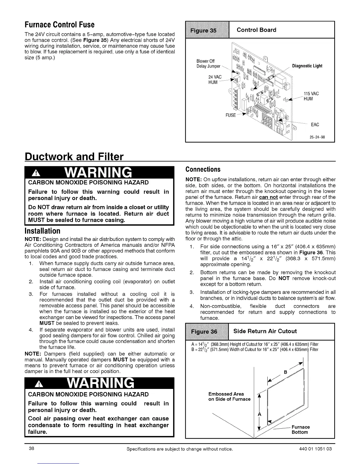
FurnaceControlFuse
The 24V circuit contains a 5-amp, automotive-type fuse located
on furnace control. (See Figure 35) Any electrical shorts of 24V
wiring during installation, service, or maintenance may cause fuse
to blow. If fuse replacement is required, use only a fuse of identical
size (5 amp.)
Control Board
iiiiiiiiiiiiiiiiiiiiiiiiiiiiiiiiiiiiiiiiiiiiiiiiiiiiiiiiiiiiiiiiiiiiiiiiiiiiiiiiiiiiiiiiiiiiiiiiiiiiiiiiiiiiiiiiiiiiiiiiiiiiiiiiiiiiiiiiiiiiiiiiiiii
BlowerOff _
DelayJumper_ _,
24VAC _d._
HUM........._-_
FU
Ductwork and Filter
CARBON MONOXIDE POISONING HAZARD
Failure to follow this warning could result in
personal injury or death.
Do NOT draw return air from inside a closet or utility
room where furnace is located. Return air duct
MUST be sealed to furnace casing.
Installation
NOTE: Design and install the air distribution system to comply with
Air Conditioning Contractors of America manuals and/or NFPA
pamphlets 90A and 90B or other approved methods that conform
to local codes and good trade practices.
1. When furnace supply ducts carry air outside furnace area,
seal return air duct to furnace casing and terminate duct
outside furnace space.
2. Install air conditioning cooling coil (evaporator) on outlet
side of furnace.
3. For furnaces installed without a cooling coil it is
recommended that the outlet duct be provided with a
removable access panel. This panel should be accessible
when the furnace is installed so the exterior of the heat
exchanger can be viewed for inspections. The access panel
MUST be sealed to prevent leaks.
4. If separate evaporator and blower units are used, install
good sealing dampers for air flow control. Chilled air going
through the furnace could cause condensation and shorten
the furnace life.
NOTE: Dampers (field supplied) can be either automatic or
manual. Manually operated dampers MUST be equipped with a
means to prevent furnace or air conditioning operation unless
damper is in the full heat or cool position.
CARBON MONOXIDE POISONING HAZARD
Failure to follow this warning could result in
personal injury or death.
Cool air passing over heat exchanger can cause
condensate to form resulting in heat exchanger
failure.
Connections
NOTE: On upflow installations, return air can enter through either
side, both sides, or the bottom. On horizontal installations the
return air must enter through the knockout opening in the lower
panel of the furnace. Return air can not enter through rear of the
furnace. When the furnace is located in an area near or adjacent to
the living area, the system should be carefully designed with
returns to minimize noise transmission through the return grille.
Any blower moving a high volume of air will produce audible noise
which could be objectionable to when the unit is located very close
to living areas. It is advisable to route the return air ducts under the
floor or through the attic.
1. For side connections using a 16"x 25" (406.4 x 635mm)
filter, cut out the embossed area shown in Figure 36. This
wilt provide a 141/2" x 221/2" (368.3 x 571.5mm)
approximate opening.
2. Bottom returns can be made by removing the knockout
panel in the furnace base. Do NOT remove knock-out
except for a bottom return.
3. Installation of locking-type dampers are recommended in all
branches, or in individual ducts to balance system's air flow.
4. Non-combustible, flexible duct connectors are
recommended for return and supply connections to
furnace.
iiiiiii_iiiiii_iiiiiiiii_i;;iiiiiIII_ii;i;_iiii11ii_iii_i!!iiiii!_iiiiiiiii!ii:i_iiiiiiiii!iiii!!iiiiii_Iiiiiiii;iiiiiiii!iiiiiii;i
SideReturnAirCutout
iiiiiiiiiiiiiiiiiiiiiiiiiiiiiiiiiiiiiiiiiiiiiiiiiiiiiiiiiiiiiiiiiiiiiiiiiiiiiiiiiiiiiiiiiiiiiiiiiiiiiiiiiiiiiiiiiiiiiiiiiiiiiiiiiiiiiiiiiiiiiiii
1
A=14/2" (368,3mm)HeightofCutoutfor16"x25"(406,4x635mm)Filter
1
B =22/2" (571.5mm)WidthofCutoutfor16"x25"(406.4x635mmFilter
Embossed Area J
on Side of Furnace _
Furttace
38 Specifications are subject to change without notice. 440 01 1051 03
 Loading...