NOTE: Furnaces with 5 ton cooling rating may require both
(left and right) side return or one side and bottom return.
Side return air duct(s) is not permitted with horizontal furnace
installation.
5. If air return grille is located close to the fan inlet, install at
least one, 90° air turn between fan and inlet grille to reduce
noise.
NOTE: To further reduce noise, install acoustical air turning vanes
and/or line the inside of duct with acoustical material.
Sizing
Existing or new ductwork MUST be sized to handle the correct
amount of airflow for either heating only or heating and air
conditioning.
Insulation
1. Insulate ductwork installed in attics or other areas exposed
to outside temperatures with a minimum of 2" (50.8mm)
insulation and vapor barrier.
2. Insulate ductwork in indoor unconditioned areas with a
minimum of 1" (25.4mm) insulation with indoor type vapor
barrier.
Filters
A Filter must be used:
Filters are not supplied with these furnaces, but can be purchased
from the distributor.
Use either filter type:
* Washable, high velocity filters are based on a maximum
air flow rating of 600 FPM.
* Disposable, low velocity filters are based on a maximum
air flow of 300 FPM when used with filter grille.
* See Circulating Air Blower Data for additional data.
NOTE: Disposable, low velocity filters may be replaced with
washable, high velocity filter providing they meet the minimum
size areas. Washable, high velocity filters can be replaced ONLY
with same type and size.
Side Mounted Filter Rack
25-20-90
FilterInstallationusingOptionalFilterRack
When installing or removing a bottom mounted filter, slide the two
side filter clips to the back of the furnace BEFORE installing or
removing. This will allow the filter to clear the front raised edge of
the furnace. Insert filter into side clips first and push filter back until
it is fully engaged into back clip. When filter is in place, slide clips
back into place midway on filter as shown in Figure 38 and
Figure 39,
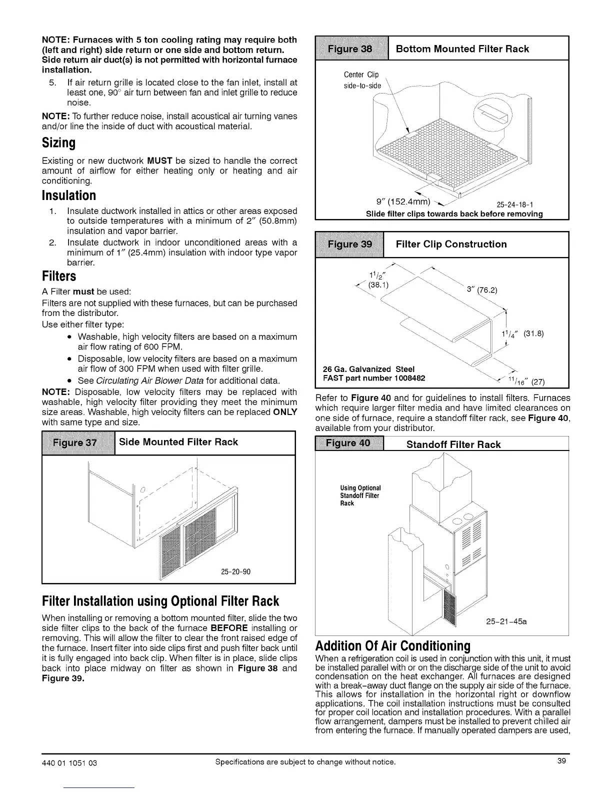
Bottom Mounted Filter Rack
9" (152.4mm) _._J 25-24-18-1
Slide filter clips towards back before removing
Filter Clip Construction
11_,, \\ _-,\
/2 j-_.. _-_.
-4_(381) _/ \\ \\-
26 Ga. Galvanized Steel -\ ).
FASTpart number 1008482 "_'_ 11/16"(27)
Refer to Figure 40 and for guidelines to install filters. Furnaces
which require larger filter media and have limited clearances on
one side of furnace, require a standoff filter rack, see Figure 40,
available from your distributor.
Standoff Filter Rack
UsingOptional
StandoffFilter
Rack
t_25-21-45a
AdditionOfAir Conditioning
When a refrigeration coil is used in conjunction with this unit, it must
be installed parallel with or on the discharge side of the unit to avoid
condensation on the heat exchanger. All furnaces are designed
with a break-away duct flange on the supply air side of the furnace.
This allows for installation in the horizontal right or downflow
applications. The coil installation instructions must be consulted
for proper coil location and installation procedures. With a parallel
flow arrangement, dampers must be installed to prevent chilled air
from entering the furnace. If manually operated dampers are used,
440 01 1051 03 Specifications are subject to change without notice. 39
 Loading...