they must be equipped with a means to prevent operation of either
unit unless the damper is in full heat or full cool position.
A 3" clearance is required on the right side of the furnace in order to
run the condensate drain line. Copper or plastic tubing may be
used for the condensate drain line.
DownflowFurnaceInstallation
Non-CombustibleFloorInstallation
Fabricate a plenum to the dimensions given in Figure 4, for the
furnace outlet. Plenum should be flanged, approximately 3/4"
(19.1 mm)for support.
Note: The three(3) screws in the top panel of the furnace next to the
duct flange MUST be removed to provide serviceability of the
primary heat exchangers in the downflow installation
1. Position plenum through the floor and set the furnace over
the opening in the floor. If necessary, grout around the base
to seal air leaks between the base and the floor.
CombustibleFloorInstallation
FIRE HAZARD
Failure to follow this warning could result in
personal injury, death, and/or property damage.
Place furnace on noncombustible subbase on
downflow applications, unless installing on
non-combustible flooring.
The noncombustible subbase also must be used
on downflow application sin addition to a coil box
installation.
Subbase for Combustible Floor
NOTE: The three(3) screws in the top panel of the furnace next to
the duct flange MUST be removed to provide serviceability of the
primary heat exchangers in the downflow installation
Note: When using the subbase for combustible floors, the
discharge air duct flanges on the furnace MUST be broken down to
provide proper fit up to the subbase. Use duct pliers to bend the
duct flanges flat onto the furnace casing. DO NOT bend the duct
flanges inward (toward the heat exchangers) as air flow restrictions
may occur.
The Subbase for Combustible Floors MUST be used when a
downflow furnace is set on a combustible floor, even when the
furnace is installed on a coil box.
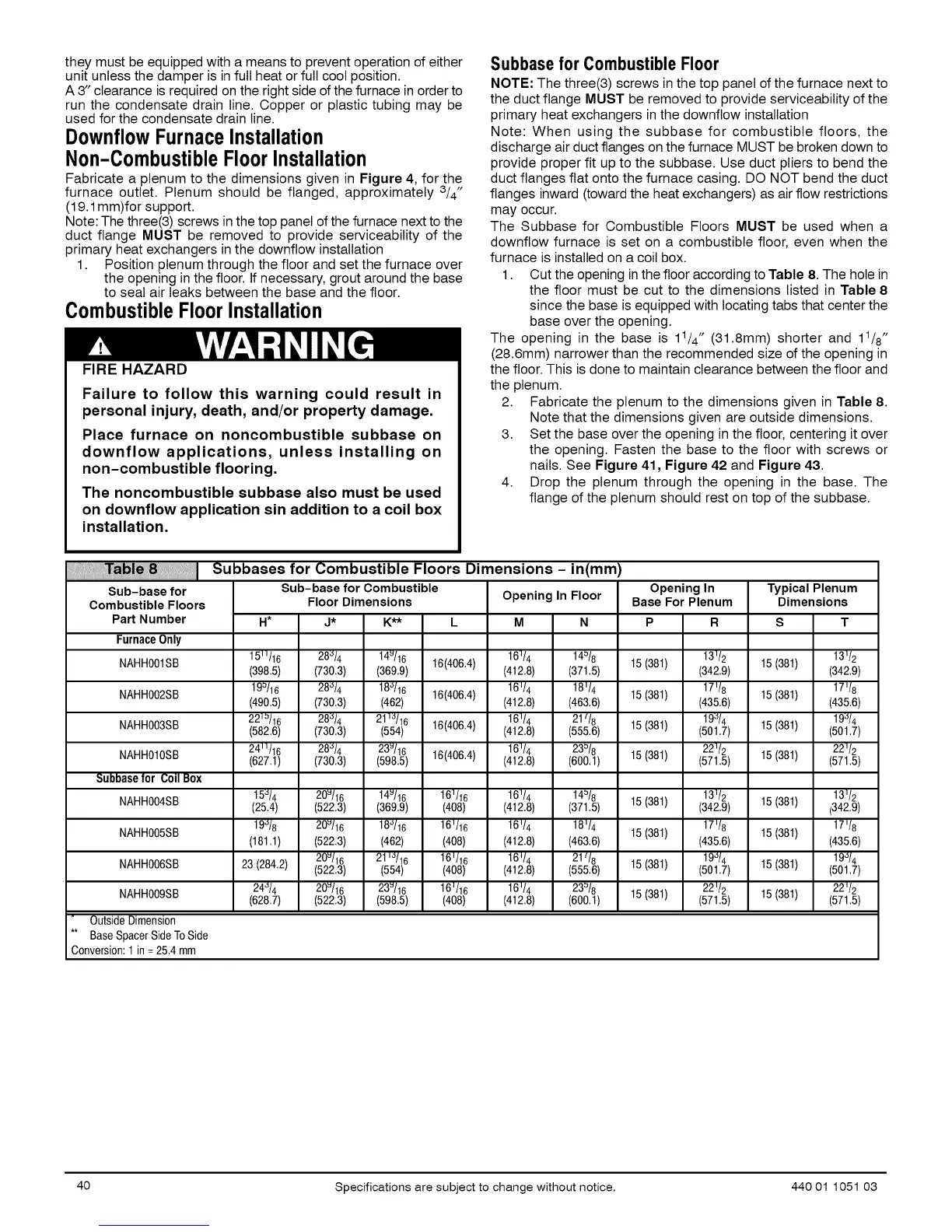
1. Cut the opening in the floor according to Table 8. The hole in
the floor must be cut to the dimensions listed in Table 8
since the base is equipped with locating tabs that center the
base over the opening.
The opening in the base is 11/4" (31.8mm) shorter and 11/8"
(28.6mm) narrower than the recommended size of the opening in
the floor. This is done to maintain clearance between the floor and
the plenum.
2. Fabricate the plenum to the dimensions given in Table 8.
Note that the dimensions given are outside dimensions.
3. Set the base over the opening in the floor, centering it over
the opening. Fasten the base to the floor with screws or
nails. See Figure 41, Figure 42 and Figure 43.
4. Drop the plenum through the opening in the base. The
flange of the plenum should rest on top of the subbase.
Sub-base for
Combustible Floors
Part Number
FurnaceOnly
1511/16 28_/4 14u/16 16(406.4)
NAHH001SB (398.5) (730.3) (369.9)
19_/16 28_/4 18_/16 16(406,4)
NAHH002SB (490.5) (730.3) (462)
221=/16 28_/4 211_/16 16(406,4)
NAHH003SB (582.6) (730.3) (554)
241t/16 28_/4 23u/16
NAHH010SB (627.1) (730.3) (598.5) 16(406.4)
Subbasefor CoilBox
15_/4 20u/16 14u/16 16_/16
NAHH004SB (25.4) (522.3) (369.9) (408)
NAHH005SB 19_/8 20_/16 18_/16 161/16
(181.1) (522.3) (462) (408)
20u/16 211"_/16 161/16
NAHH006SB 23 (284.2) (522.3) (554) (408)
24_/4 20_/16 23_/16 161/16
NAHH009SB (628.7) (522.3) (598.5) (408)
OutsideDimension
** BaseSpacerSideToSide
Conversion:1in =25.4 mm
Subbases for Combustible Floors Dimensions - in(mm)
Sub-base for Combustible
Floor Dimensions Opening In Floor
H* J* K** L M N
Opening In
Base For Plenum
P R
16_/4 14=/8 13_/2
(412.8) (371.5) 15 (381) (342.9)
16_!4 18_!4 15 (381) 17'!8
(412.8) (463.6) (435.6)
16_/4 21t/8 19_/4
(412.8) (555.6) 15 (381) (501.7)
16 _/4 23=/8 22 _/2
(412.8) (600.1) 15 (381) (571.5)
Typical Plenum
Dimensions
S
15 (381) 13V2
(342.9)
17'/8
15 (381) (435.6)
19_/4
15 (381) (501.7)
221/2
15 (381) (571.5)
16_/4 14=/8 13_/2
(412.8) (371.5) 15 (381) (342.9)
16_!4 18_!4 17V8
15 (381)
(412.8) (463.6) (435.6)
16_/4 21_/8 19"_/4
(412.8) (555.6) 15 (381) (501.7)
16_/4 23=/8 22 '/2
(412.8) (600.1) 15 (381) (571.5)
131!2
15 (381) (342.9)
17V8
15 (381)
(435.6)
19_/4
15 (381) (501.7)
22'/2
15 (381) (571.5)
40 Specifications are subject to change without notice. 440 01 1051 03
 Loading...