///il///i!!iiii/i;iiiiii!_iiii/ii!li}i¸i_iiiiii¸ii_i/iiiii/iiiiiiii///iii_ii_!ii_lii!ilii/i
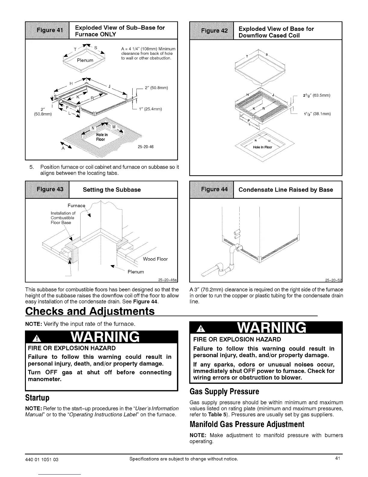
iiiii_iiiiiiiiiiiiiiiiiiiiiiiiiiiiiiiiiiiiiiiiiiiiiiiiiiiiiiiiiiiiiiiiiiii Furnace ON LY
jl_r_ s
_;_ Plenum _#_
A = 4 1/4" (108mm) Minimum
clearance from back of hole
to wall or other obstruction.
•.1, H_ I_ 2" (50.Smm)
(50.8mm) L _
5. Position furnace or coil cabinet and furnace on subbase so it
aligns between the locating tabs.
Fig_43': Setting the Subbase
iiiiiiiiiiiiiiiiiiiiiiiiiiiiiiiiiiiiiiiiiiiiiiiiiiiiiiiiiiiiiiiiiiiiiiii
J
Furnac_' \/_\
Installation of _ _IL
Combustible
Floor Base
_-_._:@::/::::: i I \._._._ Wood Floor
Plenum
25-20-46a
i i:: t: iii
Exploded View of Base for
Downflow Cased Coil
%..
_.. _
21/2" (63.5mm)
11/2" (38.1mm)
iliiiiiI! i iiCondensate Line Raised by Base
iiiiiiiiiiiiiiiiiiiiiiiiiiiiiiiiiiiiiiiiiiiiiiiiiiiiiiiiiiiiiiiiiiiiiiii
I
I
I
I
25-20-5;
This subbase for combustible floors has been designed so that the
height of the subbase raises the downflow coil off the floor to allow
easy installation of the condensate drain. See Figure 44.
Checks and Adjustments
NOTE: Verify the input rate of the furnace.
FIRE OR EXPLOSION HAZARD
Failure to follow this warning could
A 3" (76.2mm) clearance is required on the right side of the furnace
in order to run the copper or plastic tubing for the condensate drain
result in
FIRE OR EXPLOSION HAZARD
Failure to follow this warning
personal injury, death, and/or property damage.
Turn OFF gas at shut off before connecting
manometer.
line.
could result in
personal injury, death, and/or property damage.
If any sparks, odors or unusual noises occur,
immediately shut OFF power to furnace. Check for
wiring errors or obstruction to blower.
Startup
NOTE: Refer to the start-up procedures in the "User's Information
Manual" or to the "Operating Instructions Label" on the furnace.
Gas SupplyPressure
Gas supply pressure should be within minimum and maximum
values listed on rating plate (minimum and maximum pressures,
refer to Table 5). Pressures are usually set by gas suppliers.
ManifoldGas PressureAdjustment
NOTE: Make adjustment to manifold pressure with burners
operating.
440 01 1051 03 Specifications are subject to change without notice. 4t
 Loading...