1. Remove the burner compartment door.
2. Remove the blower compartment door. Place a jumper
across furnace controls R to W. Replace blower
compartment door.
3. With gas OFF, connect manometer to tapped opening on
gas valve. Use manometer with a 0 to 15 inches of water
column range.
4. Turn gas ON and remove adjustment screw cap on gas
valve. Turn adjusting screw using 3/32 hex wrench,
counterclockwise to decrease manifold pressure and
clockwise to increase pressure.
NOTE: Adjustment screw cover MUST be replaced on gas control
valve before reading manifold pressure and operating furnace.
5. Set manifold pressure to value as shown in Table 6 or
Table 7 under GAS SUPPLY AND PIPING section in this
manual.
6. When the manifold pressure is properly set, replace the
adjustment screw cover on the gas control valve.
7. Remove blower compartment door. Remove jumper wire
from thermostat connection on furnace control board.
Remove manometer connection from manifold pressure
tap, and replace plug in manifold.
8. Check for leaks at plug.
9. Replace the burner and blower compartment doors.
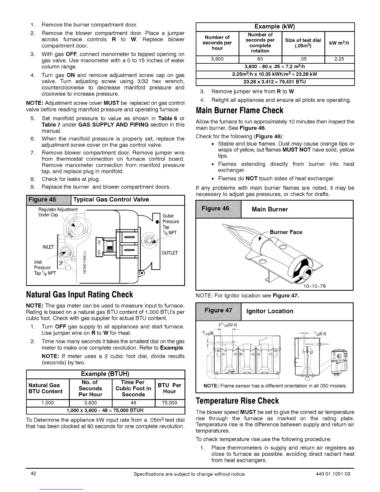
Fi_ _ _ii,ii_1Typical Gas Control Valve
RegulatorAdjustment
UnderCap
INLET
Inlet
Pressure
Tap 1/8 NPT z
Outlet
Pressure
Tap
1/8NPT
j_---
OUTLET
NaturalGasInput RatingCheck
NOTE: The gas meter can be used to measure input to furnace.
Rating is based on a natural gas BTU content of 1,000 BTU's per
cubic foot. Check with gas supplier for actual BTU content.
1. Turn OFF gas supply to all appliances and start furnace.
Use jumper wire on R to W for Heat.
2. Time how many seconds it takes the smallest dial on the gas
meter to make one complete revolution. Refer to Example.
NOTE: If meter uses a 2 cubic foot dial, divide results
(seconds) by two.
Example (BTUH)
No. of Time Per
Natural Gas BTU Per
Seconds Cubic Foot in
BTU Content Hour
Per Hour Seconds
1,000 3,600 48 75,000
1,000 x 3,600+ 48 = 75,000 BTUH
TO Determine the appliance kW input rate from a .05m3 test dial
that has been clocked at 80 seconds for one complete revolution.
Example (kW)
Number of
Number of
seconds per seconds per Size of test dial
hour complete (.05m3) kW m3/h
rotation
3,600 80 .05 2.25
3,600+ 80 x .05 = 7.2 m3/h
2.25m3/h x 10.35 kWh/m3 = 23.28 kW
23.28 x 3.412 =79,431 BTU
3. Remove jumper wire from R to W.
4. Relight all appliances and ensure all pilots are operating.
MainBurnerFlameCheck
Allow the furnace to run approximately 10 minutes then inspect the
main burner. See Figure 46.
Check for the following (Figure 46):
• Stable and blue flames. Dust may cause orange tips or
wisps of yellow, but flames MUST NOT have solid, yellow
tips.
• Flames extending directly from burner into heat
exchanger.
• Flames do NOT touch sides of heat exchanger.
If any problems with main burner flames are noted, it may be
necessary to adjust gas pressures, or check for drafts.
o,n..rner
iiiiiiiiiiiiiiiiiiiiiiiiiiiiiiiiiiiiiiiiiiiiiiiiiiiiiiiiiiiiiiiiiiiiiiiiiiiiiiiiiiiiiiiiiiiiiiiiiiiiiiiiiiiiiiiiiiiiiiiiiiiiiiiiiiiiiiiiiiiiiiii
r Face
10-10-78
NOTE: For Ignitor location see Figure 47.
, n,,or,oco,,on
iiiiiiiiiiiiiiiiiiiiiiiiiiiiiiiiiiiiiiiiiiiiiiiiiiiiiiiiiiiiiiiiiiiiiiiiiiiiiiiiiiiiiiiiiiiiiiiiiiiiiiiiiiiiiiiiiiiiiiiiiiiiiiiiiiiiiiiiiiiiiiii
21/16(52.4)
5/16(8)_ F
NOTE: Flame sensor has a different orientation in all 050 models.
TemperatureRiseCheck
The blower speed MUST be set to give the correct air temperature
rise through the furnace as marked on the rating plate.
Temperature rise is the difference between supply and return air
temperatures.
To check temperature rise,use the following procedure:
1. Place thermometers in supply and return air registers as
close to furnace as possible, avoiding direct radiant heat
from heat exchangers.
42 Specifications are subject to change without notice. 440 01 1051 03
 Loading...