iiiiii;_iiiiiiiii!iiiiiiiiii_i_Xi:iiiiii!i!_iiiii_ii;¸;iiiiiii/!ii_;_;iiiiii!iiiiiiiiiiii;;i;;i;;iiiiii;iiiii/iiiiiiiiiiiii111i/ilil
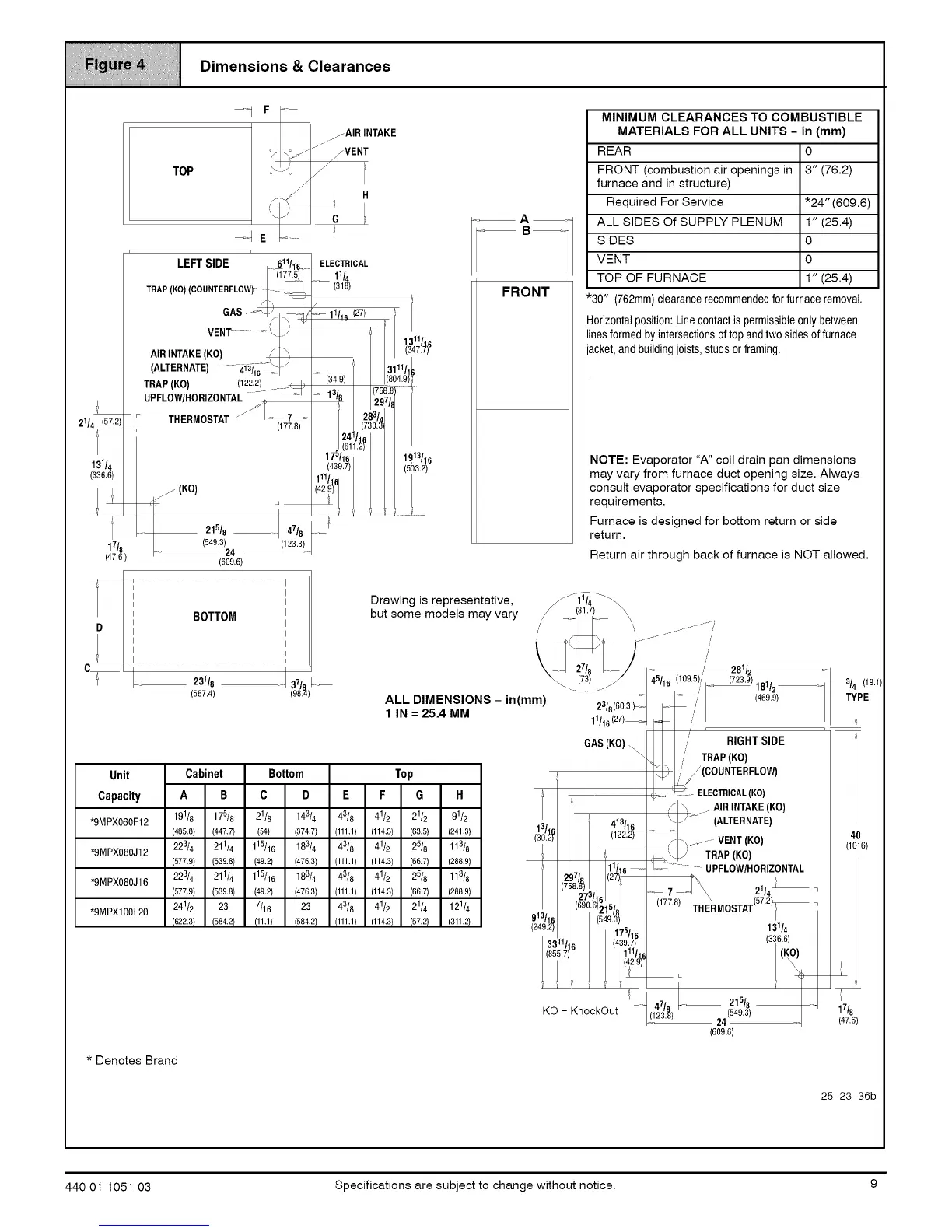
_!_i_:! I Dimensions & Clearances
iiiiiiiiiiiiiiiiiiiiiiiiiiiiiiiiiiiiiiiiiiiiiiiiiiiiiiiiiiiiiiiiiiiiiiiiiiiiiiiiiiiiiiiiiiiiiiiiiiiiiiiiiiiiiiiiiiiiiiiiiiiiiiiiiiiiiiiiiiiiiiiiiiii
21/4 (57.2)
i'
131/4
(336.6)
1 IKOl
17/6
(47.6
---1 F --
TOP
/
r n
LEFTSIDE 611/1__
TRAP (KO) (COUNTERFLOW)- (177.5t
VENT......... \_./
AIRINTAKE(KO) F _
..... 4i3116"_'\__ )(ALTERNATE)
TRAP (KO) (122.2) .... ,_)
UPFLOW/HORIZONTAL....._ _
./ /
• THERMOSTAT"j _.... 7....
• (177.8)
215/8 _ 47/8
(549.3) (123.8)
24
(609.6)
_AIR INTAKE
J
J
FVENT
/
G
T
r
ELECTRICAL
11/4
(318)
11/16(27) t
/
1311/16
(347.7)
3111/1J
_(34.9) (804.9)_
o_ 13/8 297/8
283/a
(730.3
175/16 1913/16
(439.7) (503.2)
111/16
(42.9)
/
I i ;
A
FRONT
MINIMUM CLEARANCES TO COMBUSTIBLE
MATERIALS FOR ALL UNITS - in (mm)
REAR 0
FRONT (combustion air openings in 3" (76.2)
furnace and in structure)
Required For Service
ALL SIDES Of SUPPLY PLENUM
SIDES
VENT
TOP OF FURNACE
*30" (762mm)clearancerecommendedforfurnaceremoval.
Horizontalposition:Linecontactis permissibleonly between
linesformed by intersectionsof top and twosidesof furnace
acket,and buildingjoists,studsor framing.
*24" (609.6)
1" (25.4)
0
0
1" (25.4)
NOTE: Evaporator "A" coil drain pan dimensions
may vary from furnace duct opening size. Always
consult evaporator specifications for duct size
requirements.
Furnace is designed for bottom return or side
return.
Return air through back of furnace is NOT allowed.
I
I
I BOTTOM
D I
I
I
I
L
_ 231/8
(587.4)
]
i
I
I
I
I
I
Drawing is representative, _-1T//4---_
/ _ _-_. --- 281/2
but some models may vary // ,(31.7!: _, ............ ii191/ " (7239
46/16 ,
ALLO,MENS,ONS,°=
' IN = 25.4MM - ( ) 1_:/68((6_ '3 )_= _ ,/'
Unit Cabinet Bottom Top
Capacity A B C D E F G H
*9MPX060F12 191/8 175/6 21/6 143/4 43/8 41/2 21/2 91/2
(485,8) (447,7) (54) (374,7) (111,1) (1143) (63,5) (2413)
*9MPX080J12 223/4 211/4 115/16 183/4 43/8 41/2 25/8 113/8
(577.9) (539.8) (49.2) (476.3) (111.1) (114.3) (66.7) (266.9)
*9MPX080J16 223/4 211/4 115/16 183/4 43/8 41/2 25/8 113/8
(577,9) (539,8) (49,2) (4763) (111,1) (1143) (6&7) (28&9)
*RMPXl00L20 241/2 23 7/16 23 43/6 41/2 21/4 121/4
(6223} (584,2) (11,1} (5842) (111,1} (1143} (57,2) (311,2)
GAS(KO)\
\
413/16
13/16
(30.2) (122,2)
_/6 _-
297/.8
(758.6)
273/6
(690.61215/_
913/16 (549.3
(249.2)
175/16
3311h. (439.7)
(855._1' 1111/_e
/14291
Y v v _
_- 47/8
KO= KnockOut (123.8)
/ RIGHTSIDE
.... ' TRAP(KO)
b_ _ / /
,_/ (COUNTERFLOW)
__, _ ELECTRICAL(KO)
/ \ _AIRINTAKE(KO)
"\J iS_-_ (ALTERNATE)
/ _. _.----VENT(KO)
<_ TRAPIKOI
UPFLOW/HORIZONTAL
..... 7 _,I \_ 21/4 _
(177.8) THEXRMOSTAT(57.2)_
3/4 (19.1
TYPE
L
4O
(lO16)
131/4
336.6
215/8
(549.3) 17/8
24 (47.6)
(609.6)
* Denotes Brand
25-23-36b
440 01 1051 03 Specifications are subject to change without notice. 9
 Loading...