Do you have a question about the ICP MF16J2200A and is the answer not in the manual?
Defines DANGER, WARNING, and CAUTION to identify hazard seriousness levels and potential outcomes.
Explains the usage of WARNING and CAUTION signal words within the manual for hazard communication.
Describes how signal words are used in conjunction with colors and/or pictures on product labels.
Details safety precautions, compliance with codes, and the need for qualified technicians for installation and repair.
Provides guidance on selecting the best installation site, considering structural support, service access, and environmental factors like humidity.
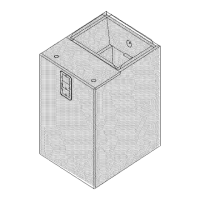
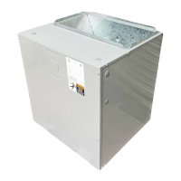
Instructions for securing the coil cabinet to the blower cabinet using tabs and applying seal strips for proper alignment and sealing.
Guidance for downflow installations, including subbase kit instructions and non-ducted return air closet setups.
Details for horizontal installations, including repositioning the drain pan for airflow direction and auxiliary drain pan requirements.
Describes methods for supporting the cabinet, including using frames, shelves, or suspension with metal strapping and threaded rods.
Ensures adequate room for service access panels and specifies placing styrofoam blocks in the auxiliary drain pan for support.
Instructions for attaching the supply duct to the unit's outlet flange, mentioning flexible connectors and clearances.
Guidance on attaching the return duct to the bottom of the unit using sheet metal screws or other fasteners.
Details on filter requirements, specifying field supply and referring to ACCA Manual D for remote filter sizing.
Specifies the necessity of power supply overcurrent protection, such as fuses or circuit breakers, according to governing codes.
Step-by-step instructions for installing the accessory No Heat Kit, including attaching plates and connecting wiring.
Details on providing and connecting line voltage power supply (208V-240V) to the unit using appropriate terminals and copper wire.
Instructions for making a proper ground connection using a copper conductor from the unit to a grounded connection in the electric service panel or grounding rod.
Explains the 24-volt power supply, transformer tapping, wiring entry, and connection at the control board terminals for various configurations.
Provides instructions on how to change the blower motor speed by disconnecting and reconnecting wires at the terminal block.
Guidance on setting the heat anticipator of the thermostat to the proper value according to thermostat manufacturer instructions.
Details how electric heater elements are staged using control signals to W1 and W2 terminals, including jumpering for simultaneous staging.
Details the process of measuring external static pressure at supply and return duct connections to determine airflow and select motor speed.
Referencing Air Flow Data tables and motor speed instructions to select the correct speed tap for required airflow.
Step-by-step instructions to check the temperature rise across the unit by measuring supply and return air temperatures during heating operation.
Note that temperature rise can be adjusted by changing the heating speed tap at the unit's blower terminal block.
Instructions for cleaning external filters, emphasizing inspection frequency and its impact on unit efficiency.
States that the bearings of the blower motor are permanently lubricated.
Guidance on checking condensate drain lines during cooling season to ensure proper flow and prevent blockages.
Details the sequence of operation for various modes including Electric Heat Only, Cooling Only, and Heat Pump, with and without electric heat.
Explains how the temperature limit responds to over-temperature conditions, including soft and hard lockout procedures.
Lists replacement parts with corresponding part numbers for various Modular Blower models, including controls, motors, and panels.