I
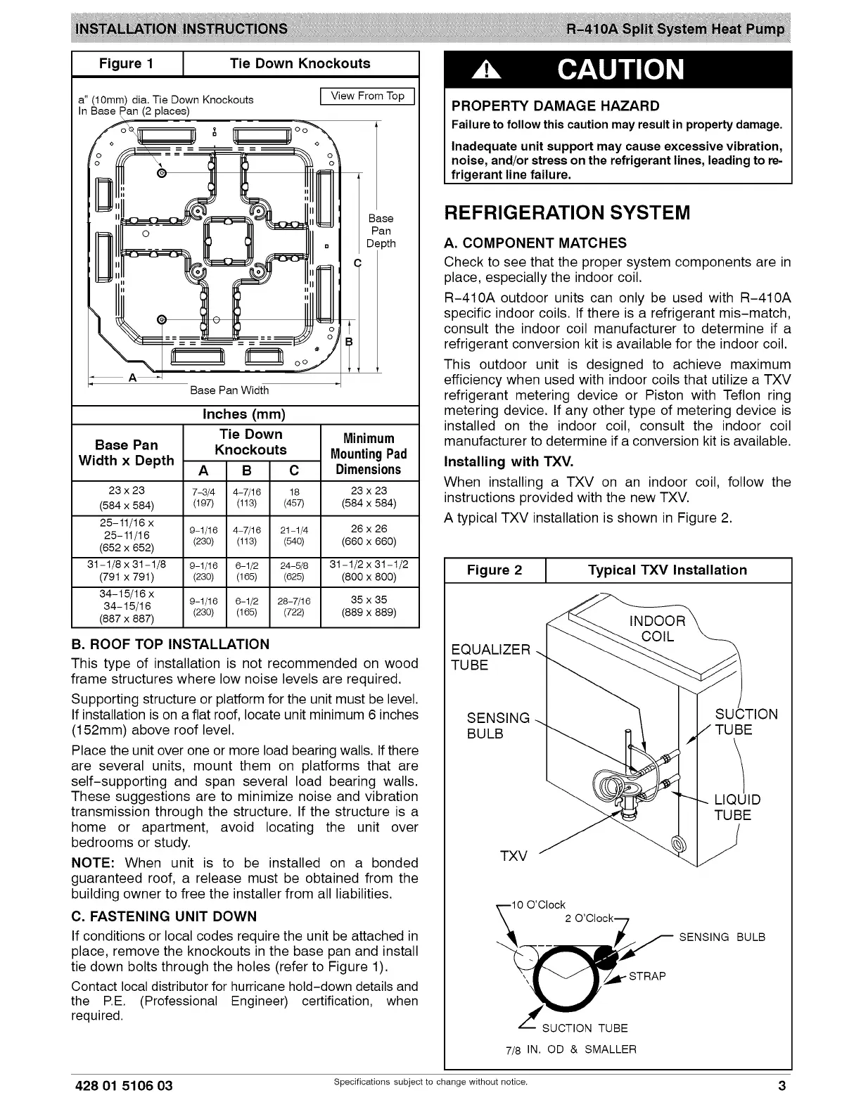
Figure 1 J Tie Down Knockouts
a" (10mm) dia. Tie Down Knockouts [ View From Top
In Base Pan (2 places)
Base
Pan
Depth
o o
A
Base Pan Width
Base Pan
Width x Depth
23 x 23
(584 x 584)
25-11/16 x
25-11/t6
(652 x 652)
31-1/8 x 31-1/8
(791 x 791)
34-15/16 x
34-15/16
(887 x 887)
Inches (mm)
Tie Down
Knockouts
A
7-3/4
(197)
9-1/16
(230)
9-1/16
(230)
B C
4-7/16 18
(113) (457)
4-7/16 21-1/4
(113) (540)
6-1/2 24-5/8
(165) (625)
9-1/16 6-1/2 28-7/16
(230) (165) (722)
Minimum
MountingPad
Dimensions
23 x 23
(584 x 584)
26 x 26
(660 x 660)
31-1/2 x 31 -t/2
(800x800)
35 x 35
(889 x 889)
B. ROOF TOP INSTALLATION
This type of installation is not recommended on wood
frame structures where low noise levels are required.
Supporting structure or platform for the unit must be level.
If installation is on a flat roof, locate unit minimum 6 inches
(152mm) above roof level.
Place the unit over one or more load bearing walls. If there
are several units, mount them on platforms that are
self-supporting and span several load bearing walls.
These suggestions are to minimize noise and vibration
transmission through the structure. If the structure is a
home or apartment, avoid locating the unit over
bedrooms or study.
NOTE: When unit is to be installed on a bonded
guaranteed roof, a release must be obtained from the
building owner to free the installer from all liabilities.
C. FASTENING UNIT DOWN
If conditions or local codes require the unit be attached in
place, remove the knockouts in the base pan and install
tie down bolts through the holes (refer to Figure 1).
Contact local distributor for hurricane hold-down details and
the RE. (Professional Engineer) certification, when
required.
PROPERTY DAMAGE HAZARD
Failure to follow this caution may result in property damage.
Inadequate unit support may cause excessive vibration,
noise, and/or stress on the refrigerant lines, leading to re-
frigerant line failure.
REFRIGERATION SYSTEM
A. COMPONENT MATCHES
Check to see that the proper system components are in
place, especially the indoor coil.
R-410A outdoor units can only be used with R-410A
specific indoor coils. If there is a refrigerant mis-match,
consult the indoor coil manufacturer to determine if a
refrigerant conversion kit is available for the indoor coil.
This outdoor unit is designed to achieve maximum
efficiency when used with indoor coils that utilize a TXV
refrigerant metering device or Piston with Teflon ring
metering device. If any other type of metering device is
installed on the indoor coil, consult the indoor coil
manufacturer to determine if a conversion kit is available.
Installing with TXV.
When installing a TXV on an indoor coil, follow the
instructions provided with the new TXV.
A typical TXV installation is shown in Figure 2.
Figure 2 [ Typical TXV Installation
EQUALIZER
TUBE
SENSING
BULB
SUCTION
TUBE
LIQUID
TUBE
TXV
_.--10 O'Clock
'_ 2 O'Clock 7
__T/U__BE STRAP
7/8 IN. OD & SMALLER
SENSING BULB
428 01 5106 03 Specifications subject to change without notice. 3
 Loading...