transmission between the tubing and the foundation or
wall.
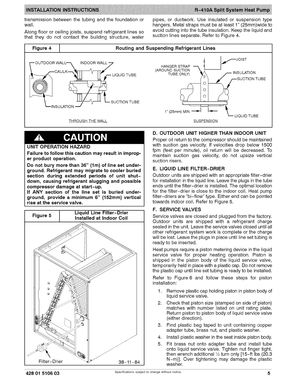
Along floor or ceiling joists, suspend refrigerant lines so
that they do not contact the building structure, water
pipes, or ductwork. Use insulated or suspension type
hangers. Metal straps must be at least 1" (25mm)wide to
avoid cutting into the tube insulation. Keep the liquid and
suction lines separate. Refer to Figure 4.
Figure 4
1
Routing and Suspending Refrigerant Lines
OUTDOOR WALL's. INDOOR WAL_7
I_CAU LK_,,_f-i-i_ V_i-F_ ¥
_ LIQUID TUBE
--'?___NSU LATI ON y-_ SUCTION TUBE
THROUGH THE WALL
HANGER STRAP "_
(AROUND SUCTION _,= --
TUBE ONLY) _
1" (25mm) MIN ._D,.--I I_
LIQUID
lf JOiST
t_:U cTLA:IoONNTUB E
'4
TUBE
SUSPENSION
UNIT OPERATION HAZARD
Failure to follow this caution may result in improp-
er product operation.
Do not bury more than 36" (lm) of line set under-
ground. Refrigerant may migrate to cooler buried
section during extended periods of unit shut-
down, causing refrigerant slugging and possible
compressor damage at start-up.
If ANY section of the line set is buried under-
ground, provide a minimum 6" (152mm) vertical
rise at the service valve.
Figure 5 1
Liquid Line Filter-Drier
Installed at Indoor Coil
\
Filter-Drier
38-11-84
D. OUTDOOR UNIT HIGHER THAN INDOOR UNIT
Proper oil return to the compressor should be maintained
with suction gas velocity. If velocities drop below 1500
fpm (feet per minute), oil return will be decreased. To
maintain suction gas velocity, do not upsize vertical
suction risers.
E. LIQUID LINE FILTER-DRIER
Outdoor units are shipped with an appropriate filter-drier
for installation in the liquid line. Leave the plugs in the tube
ends until the filter-drier is installed. The optimal location
for the filter-drier is close to the indoor coil. Heat pump
filter-driers are "bi-flow" type. Either end can be pointed
towards indoor coil. Refer to Figure 5.
F. SERVICE VALVES
Service valves are closed and plugged from the factory.
Outdoor units are shipped with a refrigerant charge
sealed in the unit. Leave the service valves closed until all
other refrigerant system work is complete or the charge
will be lost. Leave the plugs in place until line set tubing is
ready to be inserted.
Heat pumps require a piston metering device in the liquid
service valve for proper heating operation. Piston is
shipped in the piston body of the liquid service valve,
temporarily held in place with a plastic cap. Do not remove
the plastic cap until line set tubing is ready to be installed.
Refer to Figure 6 and follow these steps for piston
installation:
1. Remove plastic cap holding piston in piston body of
liquid service valve.
2. Check that piston size (stamped on side of piston)
matches with number listed on unit rating plate.
Return piston to piston body of liquid service valve
(either direction).
3. Find plastic bag taped to unit containing copper
adapter tube, brass nut, and plastic washer.
4. Install plastic washer in the seat inside piston body.
5. Fit brass nut onto adapter tube and install tube
onto liquid service valve. Tighten nut finger tight,
then wrench additional 1/2turn only [15-ft Ibs (20.3
N-m)]. Over tightening may damage the plastic
washer.
428 01 5106 03 Specifications subject to change without notice. 5
 Loading...