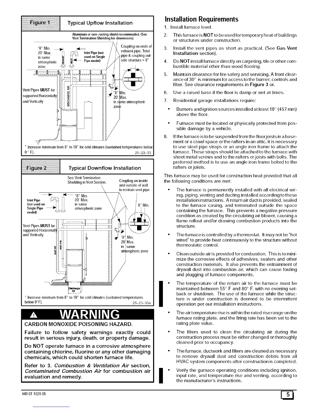
Typical Upflow Installation
Aluminumor non-rustingshield recommended.(See
VentTerminationShieldingfor dimensions).
Coupling on ends of
*8" Min. _l[q _I_ exhaust pipe. Total
20' Max. Inlet Pipe(not
in same _ _ usedon Single pipe & coupling out-
atmospheric <_ __4t_ Pipe model) side structure = 8"
zone
VentPipes MUSTbe
/]in.
supported
and Vertically me atmospheric
* Increase minimum from 8" to 18" for cold climates (sustained temperatures below
0 ° F). 25-23-33
Typical Downflow Installation
See VentTermination
Shieldingin VentSection.
_1 14' _8" Min.
InletPipe _ [_ 20' Max.
(not usedon _ _ in same
SinglePipe _ I,,,_ L, atmospheric zone
model) _
Vent Pip MUSTbq
support( 4orizonta
and Vertically
Coupling on inside
and outside of wall
to restrain vent pipe
Min.
Max.
same
osphericzone
Increase minimum from 8" to 18" for cold climates (sustained temperatures
below O°F). 25-23-33a
CARBON MONOXIDE POISONING HAZARD.
Failure to follow safety warnings exactly could
result in serious injury, death, or property damage.
Do NOT operate furnace in a corrosive atmosphere
containing chlorine, fluorine or any other damaging
chemicals, which could shorten furnace life.
Refer to 3. Combustion & Ventilation Air section,
Contaminated Combustion Air for combustion air
evaluation and remedy.
Installation Requirements
1. Install furnace level.
2. This furnace is NOT to be used for temporary heat of buildings
or structures under construction.
3. Install the vent pipes as short as practical. (See Gas Vent
Installation section).
4. Do NOT install furnace directly on carpeting, tile or other com-
bustible material other than wood flooring.
5. Maintain clearance for fire safety and servicing. A front clear-
ance of 30" is minimum for access to the burner, controls and
filter. See clearance requirements in Figure 3 or.
6. Use a raised base if the floor is damp or wet at times.
7. Residential garage installations require:
• Burners and ignition sources installed at least 18" (457 mm)
above the floor.
8.
Furnace must be located or physically protected from pos-
sible damage by a vehicle.
If the furnace is to be suspended from the floor joists in a base-
ment or a crawl space or the rafters in an attic, it is necessary
to use steel pipe straps or an angle iron frame to attach the
furnace. These straps should be attached to the furnace with
sheet metal screws and to the rafters or joists with bolts. The
preferred method is to use an angle iron frame bolted to the
rafters or joists.
This furnace may be used for construction heat provided that all
the following conditions are met:
The furnace is permanently installed with all electrical wir-
ing, piping, venting and ducting installed according to these
installation instructions. A return air duct is provided, sealed
to the furnace casing, and terminated outside the space
containing the furnace. This prevents a negative pressure
condition as created by the circulating air blower, causing a
flame rollout and/or drawing combustion products into the
structure.
• The furnace is controlled by a thermostat. It may not be "hot
wired" to provide heat continuously to the structure without
thermostatic control.
Clean outside air is provided for combustion. This is to mini-
mize the corrosive effects of adhesives, sealers and other
construction materials. It also prevents the entrainment of
drywall dust into combustion air, which can cause fouling
and plugging of furnace components.
I • The temperature of the return air to the furnace must be
maintained between 55 ° F and 80 ° F, with no evening set-
back or shutdown. The use of the furnace while the struc-
ture is under construction is deemed to be intermittent
operation per our installation instructions.
The air temperature rise is within the rated rise range on the
furnace rating plate, and the firing rate has been set to the
rating plate value.
The filters used to clean the circulating air during the
construction process must be either changed or thoroughly
cleaned prior to occupancy.
The furnace, ductwork and filters are cleaned as necessary
to remove drywall dust and construction debris from all
HVAC system components after construction is completed.
• Verify the gurnace operating conditions including ignition,
input rate, and temperature rise and venting, according to
the manufacturer's instructions.
44001 102005 [_
 Loading...
