Product Key
IL Series digital
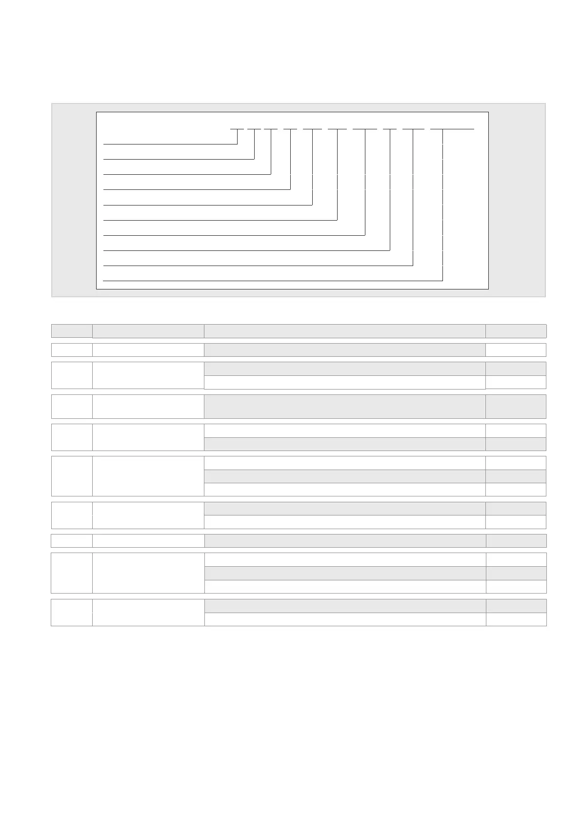
The 16 character alphanumeric order number for the desired type is composed of the order code listed below.
1 2 3 4 5 6 7 8 9 10 11 12 13 14 15 16
Series
Design
Physical outputs
Output signals
Operating conditions / Special versions
Measured variable and output range 1
Measured variable and output range 2
Supply voltage
Measuring head / Filter / Diameter
Design description
Technical Data Options Order Code
1
Series IL Series
L
2
Design Duct version
K
Wall mounting
W
3
Physical outputs Humidity and Temperature, dew point temperature (°C), enthalpy (kJ/kg),
mixing ratio (g/kg), absolute humidity (g/m³) and wet-bulb temperature (°C)
K
4
Output signals
RS232 ASCII protocol R
RS485 MODBUS RTU protocol M
5 6
Operation conditions /
special versions
Standard
00
Sealing against vibrations (optional)
0V
Sealing for increased requirements (e.g. condensation, optional)
0S
7 8 output range
1
relative humidity and humidity dependant hx values F1
9 10 output range
2
-40...85 °C 48
11 Supply voltage 5...30 V DC 5
12 13 Measuring head /
lter / diameter
ZE05: PTFE sintered lter, Ø 12 mm 05
ZE07: protective cage, plastic, open, Ø 12 mm 07
ZE08: protective cage, plastic, with membrane, Ø 12 mm 08
14 15 16 Description of design Duct sensor, sensor tube length 220 mm (standard) 00 G
Wall mounting, sensor tube length 50 mm (standard) 00 1